Thursday, June 29, 2017

Time to Use CPAK Transceiver for 100G Network Deployment

Over the past few years, we gave a warm welcome to 100G network market, for meeting our ever-increasing demand. With the prosperous development of 100G optical technology, several 100G transceivers like CFP, CFP2, CFP4, QSFP28 have come out that we may be very familiar with. Except for these common 100G transceivers, CPAK transceiver also plays an important role in 100G network that would be a good choice if you need to deploy a 100G network. What’s the benefits of CPAK transceiver, compared to other 100G transceivers? Why it is an ideal solution to deploy 100G network with CPAK transceiver? Let’s talk about this topic.

Introduction to 100G CPAK Transceiver
CPAK transceiver module is a kind of hot-swappable I/O component for inserting into 100G Ethernet Port of Cisco switch and router, published in 2013 by Cisco. This kind of transceiver has generally 82 pins on its electrical interface, 40 of which are on the top row and 42 on the bottom row. While on its optical interface, there is a duplex SC or 24-fiber MPO connector. In contrast to other optical transceivers, 100G CPAK is distinctive, designed on the basis of complementary metal-oxide semiconductor (CMOS) photonics technology, which features the advantages of high optical integration, performance, power savings, and scalability.

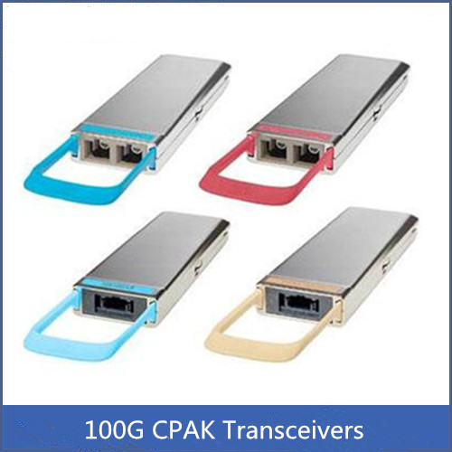
CPAK transceiver has the greatest density and bandwidth but the lowest power consumption which is an ideal 100G solution for data center, enterprise and edge networks. To well serve 100G demand, it has several types like CPAK 100G SR10, CPAK 100G ER4L, CPAK 100G LR4 with different IEEE-standard optical interfaces that can support 100G connections with different distances. You can learn some common CPAK transceivers with different optical interfaces from the figure below.

100G CPAK transceiver consist of CPAK 100G SR10, CPAK 100G ER4L, CPAK 100G LR4, and etc.

Benefits of 100G CPAK Transceiver
To face the exploding demand of network bandwidth, 100G solution came into the market with high cost. Under this condition, experts turn to explore the high density but cost effective solution to make the 100G network commonly deployed. And the 100G CPAK transceiver is just the alternative to the existing 100G transceiver that has higher port density and power saving. Let’s learn the main benefits of this kind of 100G transceiver.

Firstly, 100G CPAK transceiver is designed on the basis of COMS technology which solves the limitation of optical interconnect technology. As we know, COMS photonics is a technology that can control the flow of photons in place of electrons by integrating multiple circuit components in a highly efficient design, and then printing entire circuits directly on silicon wafers to produce optical devices. Hence, the 100G CPAK transceiver utilizing COMS technology has a smaller footprint but higher port density, which enables extremely efficient, low-power optical circuits.

Secondly, CPAK transceiver is a 100G power saving and high density transceiver solution, addressing the existing 100G transceivers’ big physical size, excessive heat and power problems. Different from the existing 100G transceivers, CPAK transceiver is designed to decrease the space and power requirements by over 70 percent, while improving the port density and front-panel bandwidth up to 20 percent. It has great improvements in size, power consumption, density and bandwidth for facing the increasing need to scale data center and networking equipment.

Conclusion
CPAK transceiver is an economical choice to deploy 100G network which exceedingly solve the big size and excessive power problems in the existing 100G transceivers. Considering that, 100G CPAK transceiver modules like CPAK 100G SR10, CPAK 100G ER4L, CPAK 100G LR4 are available on the market, with very good price and quality assurance, for better serving 100G users.

Friday, June 9, 2017

Analysis of Power Budget and Link Distance in CWDM System

It can’t be denied that CWDM technology is a cost effective method to increase the capacity in the existing system, which can give different wavelengths to multiple optical signals and multiplex them for transmission through only one single fiber. Different from the DWDM system, the network using CWDM technology are deployed by passive components like passive CWDM Mux Demux, without the need of additional power, which makes CWDM system more commonly used. Do you also plan to build a CWDM system? If yes, you can check the following information for reference, which mainly analyzes the optical power budget in a CWDM system and calculates the CWDM link distance according to the power budget for smoothly deploying a CWDM system.

What’s Optical Power Budget?
Before deploying an optical network, it is very essential to calculate the optical power budget for better deployment. What’s optical power budget? It is just the amount of light available to make a successful fiber connection which can be calculated by analyzing the original output power of the transmitter and the required input power of the receiver. In details, we should firstly learn the optical power that is emitted by the source (also referred to Transmit Power) and the required power of the detector (also called Receiver Sensitivity). Using the first data to subtract the second one, you’ll get the data of the optical power budget which greatly determines the performance of the whole network link.

Here is the equation: Optical Power Budget = Transmit Power - Receiver Sensitivity.

How to Get the Optical Power Budget in a CWDM System?
To estimate the link distance supported by a CWDM system, the optical power budget should be calculated first, which can greatly determine the CWDM link distance. Here will show you a basic CWDM system under an ideal condition to clearly illustrate how to get the optical power budget. In this basic CWDM system, there is a optical transmitter which transmit power is -2 dBm and a optical receiver with -25 dBm receiver sensitivity. Hence, the optical power budget is 23 dB, as shown in the following equation.

Optical Power Budget = Tx Power - Rx Sensitivity = -2 dBm - (-25 dBm) = 23 dB

However, the mentioned CWDM system is just under an ideal condition without loss caused by the signal transmission. In a normal CWDM system, there are many components like passive CWDM Mux Demux, CWDM transceiver inserted. All these components cause insertion loss once they are inserted into the CWDM link. Therefore, when doing the optical power budget, all the loss should be taken into account for calculating the power budget exactly.

Here is more exact equation: Power Budget = Tx Power - Rx Sensitivity - Loss

To get the real power budget of a CWDM system, here offers a simple CWDM link which uses the -2 dBm optical transmitter, -25 dBm optical receiver and four passive CWDM Mux Demux with low insertion loss. Both the stable 4 channel CWDM Mux and stable 4 channel CWDM Demux in the link have 2.0 dB insertion loss, and other two are 8 channel ones feature 2.5dB insertion loss separately, as shown in the figure below. As a result, the total loss caused by the four passive CWDM Mux Demux is 9 dB, resulted from 2.5 dB + 2.0 dB+2.5 dB + 2.0 dB. Then we can get the total power budget, 14 dB. The calculation process is: Power Budget = Tx Power - Rx Sensitivity - Loss = -2 dBm - (-25 dBm) - 9 dB = 14 dB

Power Budget for CWDM Network

How to Calculate the Link Distance in the CWDM System?
After knowing the optical power budget, let’s calculate the link distance of the CWDM system according to the following equation: Link Distance = Optical Power Budget/Fiber Attenuation. As there may be some other power loss caused by the factors that we didn’t consider like fiber aging, temperature and poor splice, we often subtract 2 dB buffer from the total optical power budget. Meanwhile, the fiber attenuation is changeable according to the wavelength, usually varying from 0.2 to 0.35 dB/km. In this case, we’ll use 0.35 dB/km as a typical data. Then we can get the link distance is about 34 km. The calculation process is Link Distance = Optical Power Budget/Fiber Attenuation = (14 dB- 2 dB)/0.35 dB/km.

Conclusion
This paper intends to illustrate how to calculate the optical power budget and estimate the link distance of a CWDM system according to the optical power budget, which allows for better budget of deploying the CWDM system and eliminates the unwanted or unnecessary issues which may happen in the system deployment. Besides, if you want to make a cost effective CWDM system, you are suggested to buy CWDM components like cheap passive CWDM Mux Demux, CWDM transceivers from FS.COM, which are of good price and quality.

Monday, June 5, 2017

What Can CATV Systems Benefit from EDFA Optical Amplifiers?

As long-distance transmissions are always required in the CATV systems, it is very necessary to make the quality of visual and audio signals in high levels after the long transmissions, so that the performance of the CATV systems can be ensured. To serve this aim, the CATV EDFA optical amplifiers are come up with and widely used in the CATV systems. Why the EDFA optical amplifier is needed in CATV system? How does it work for the long CATV application? The following text will give you the answers and simply introduce two typical CATV EDFA amplifier applications for your reference.

What’s CATV EDFA Amplifier?
CATV EDFA is a kind of optical amplifier, most commonly used in the long-haul CATV system for boosting the damped CATV signals, with the aim of compensating the signal loss. Since it mostly works as booster optical amplifier in the CATV system, so that it can be also called CATV booster amplifier. By utilizing the CATV EDFA optical amplifier, the CATV signals can be enhanced to meet the system requirement and then be sent to the users. However, when the signal power is improved by the CATV EDFA, the noise existing in the transmission link would also boosted and some return loss would also occur at the same time. Considering that, it is very necessary to choose quality CATV EDFA optical amplifier for ensuring the performance of CATV system, even if it may be cost a little higher than common optical amplifier.

Why CATV EDFA Optical Amplifier is Used?
CATV is a multi-channel TV system transmitting visual and audio signals from digital or analog television and radio channel to many users via fiber or copper patch cable. As the signals should be finally separated by optical splitter to serve more than one users and many loss has occurred in the long transmission, the overall speed and quality of the CATV signals would become too weak to meet the receiver requirements. Under this condition, the CATV EDFA optical amplifier is very essential for CATV system with the function of amplifying CATV signals and giving high performance systems to the users.

How Does CATV EDFA Work for Long CATV Applications?
A long CATV system is always composed of head end, transmitter, receiver, CATV booster amplifier and optical splitter. When the system runs, the CATV signals are provided by the head end, and need to be split into several signals by the optical splitter to serve the users. When the signals pass through the optical splitter, the signal power would be in a very low level. Hence, the CATV EDFA optical amplifier should be deployed after the receiver to improve the signal power, and the users can finally receive quality signals.

http://www.chinacablesbuy.com/wp-content/uploads/2017/06/CATV-EDFA-Optical-Amplifier

From the figure above, we can learn a simple point-to-multipoint CATV network design as mentioned above. The CATV signals are provided by the RF combiner and should be connected with four receivers by the optical splitter. In order to compensating the signal loss caused by the optical splitter, CATV EDFA optical amplifier is required before sending the weak signals to the users.

Except for this simple kind of CATV network using CATV EDFA optical amplifier, here also offers a complex CATV network, as designed in the figure below. In this CATV network, the CATV EDFA optical amplifier is deploy behind the 8 channel DWDM Mux Demux to amplify the signals while the 8 channel DWDM Mux Demux allows for higher capacity transmission. Hence, a long CATV network with big capacity can be achieved.

 CATV EDFA Optical Amplifier with DWDM Mux

Conclusion
When deploying a long CATV system, we should pay attention to the loss caused by long transmission distance and CATV components. When the loss is very high, CATV EDFA optical amplifier would be an ideal device deployed in the long CATV system for improving the quality of CATV signals, so that the users can receive high speed and reliability of the services.

Thursday, June 1, 2017

EDFA Amplifiers for Building Long-haul DWDM Networks

Clearly different from the traditional repeater, the EDFA amplifier doesn’t need to convert the optical signals into electrical ones, then make the electrical amplification and finally convert the amplified electrical signals into amplified optical signals again. It is an optical amplifier that can directly enhance the optical signals without making additional conversion. By using the EDFA optical amplifier, the attenuated signal power can be amplified into strong signal level to meet the requirement of the long-haul applications, especially the long-haul DWDM networks. To better understand the function of EDFA amplifier, the following will mainly study the working principle of EDFA amplifier works and illustrate how to use it to build the long DWDM network.

What’s the Working Principle of EDFA Amplifier?
From the figure below, we can learn the basic configuration of the EDFA amplifier, mainly composed of a length of EDF (erbium doped fiber), a pump laser with 980 nm or 1480 nm, a pump combiner and a simple WDM system. When the attenuated signals around 1550 nm pass through an EDFA amplifier, a pump laser will be generated. Then the DWDM signals and pump laser will be combined by the pump combiner. When they come into the EDF together, the wavelengths of signals and pump laser will be multiplexed and the interaction with the doping ions would enhance the signal power into high level. Thereby, a longer DWDM transmission can be reached.

EDFA Amplifier Configuration

How to Use EDFA Amplifier for Long DWDM network?
In a long DWDM network, the EDFA amplifier can be put in three different places with different aims. Firstly, we can put it in the transmitter side of the DWDM link to offer high input signal power, so that the DWDM fiber link can be extended. If the EDFA amplifier is deployed in this place, we can also call it EDFA optical booster amplifier. Secondly, we can also place the EDFA amplifier in the receiver side of the DWDM link as optical preamplifier, hence the output signal power can be boosted to meet the necessary receiver level. Finally, when the fiber loss in the transmission process is too high to support the long DWDM network, we can deploy the EDFA amplifier in any intermediate point along the long fiber link to compensate the fiber loss. And this time, we can call it EDFA optical in-line amplifier.

Analysis of Practical Long DWDM Cases with EDFA Amplifiers
Case One: in this case, EDFA optical booster amplifiers are deployed at both transmitter sides of the dual-way DWDM links. We can learn it from the figure below. Two 40 channel DWDM Mux Demux are deployed to multiplex 40 1G signals. Then the two integrated 40G signals from both sides are enhanced by the booster amplifier and can be transmitted up to 170 km over each single fiber.

EDFA Optical Booster Amplifier

Case Two: as shown in the following figure, except for the booster amplifiers, EDFA optical optical preamplifiers are also placed at both receiver sides of the dual-way DWDM links. By adding the optical preamplifiers to the CWDM link, the transmission distance is finally extended from 170 km to 200 km.

EDFA Optical Preamplifier

Case Three: it is highly noted from the following figure that the DWDM transmission distance can be up to 400 km. How to achieve this? Just putting the EDFA amplifiers in the three places mentioned above. As deployed in the figure, a pair of EDFA optical booster amplifiers, optical preamplifiers and optical in-line amplifiers are used for the 400km transmission.

EDFA Optical in-line Amplifier

Case Four: If the distance of 400 km still cannot meet our requirement, we can set up more repeater sites to place other optical in-line amplifiers. At present, using these three kinds of EDFA amplifiers already enables 100Gbps bandwidth for realizing up to 1000 km in a point-to-point connection, as shown in the figure below.

EDFA Amplifiers for 100G 1000km Tranmission

Conclusion
When designing a long-haul DWDM network for transmitting big data, EDFA amplifier is an ideal solution for current and future optical system which should be taken into consideration. It can be deployed at the transmitter side, the receiver side and any intermediate point along the DWDM long fiber link, as optical preamplifier, booster amplifier and in-line amplifier, for enhancing the signal power, thereby a long-haul transmission can be deployed.