Thursday, July 13, 2017

Comparison of Passive DWDM and Active DWDM System

DWDM (dense wavelength division multiplexing) technology is an ideal solution to address the capacity-hungry issue, which can simply fall into two types, passive DWDM and active DWDM. To greatly expand the bandwidth of the existing fiber system, both passive DWDM and active DWDM systems are designed to multiplex different wavelengths for carrying multiple signals over one single fiber. To better know the features of these two DWDM systems, the following will intend to learn what are the passive DWDM and active DWDM systems, and find their advantages and disadvantages.

Passive DWDM System Overview
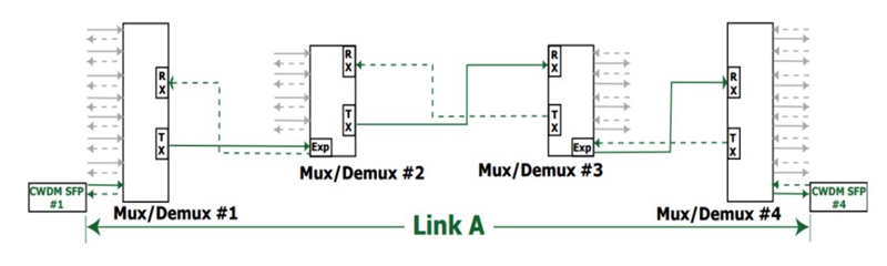
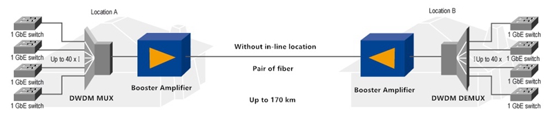
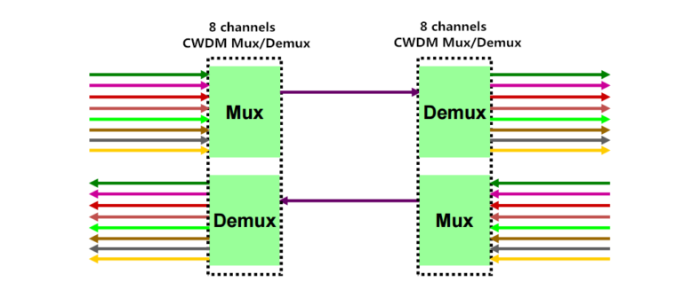
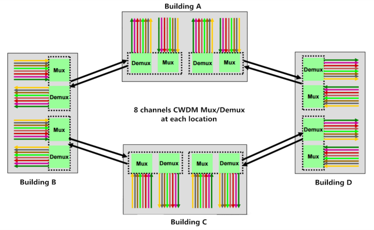
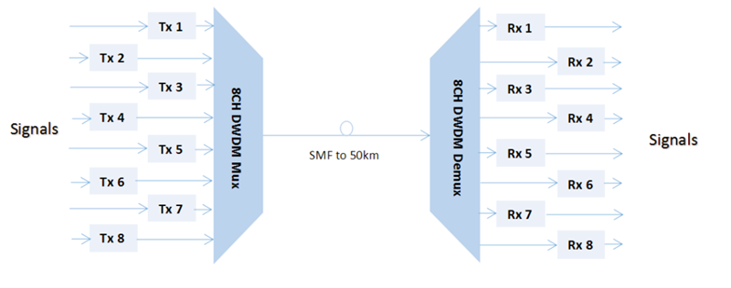
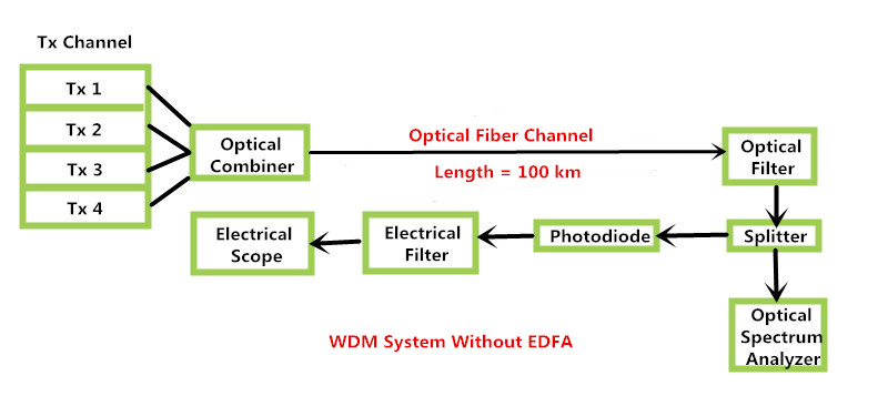
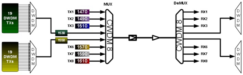
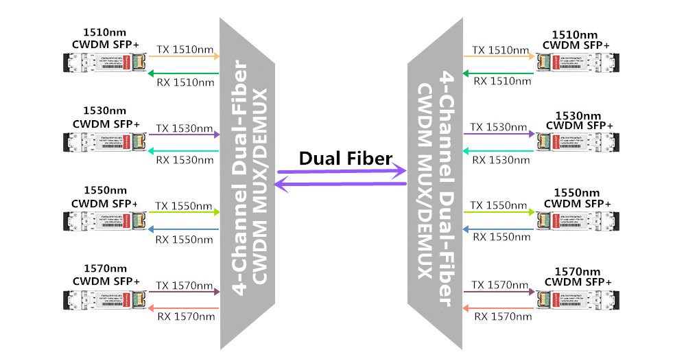
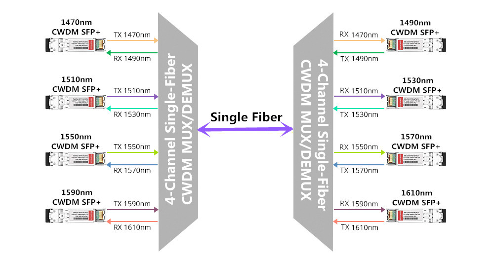
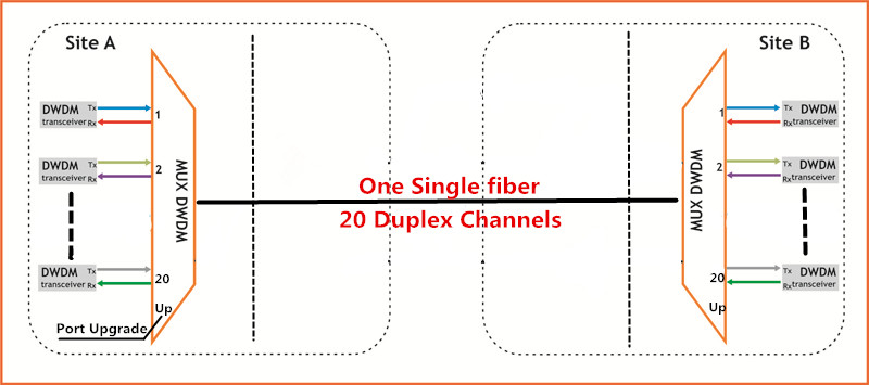
Since there is no any active component used in the passive DWDM system, the performance of the passive DWDM link only depends on the optical budget of the DWDM transceivers used in the system. That’s to say, the transmission distance the passive DWDM system supports can’t be extended and is limited to the optical budget of the DWDM transceivers. We can learn from the figure below that shows a common passive DWDM system. Obviously, no active component like fiber amplifier and DCM module, but a pairs of 20 channels DWDM Mux are used. This design allows for high capacity transmission and makes capacity expansion possible. In short, it is very suitable to deploy passive DWDM system in metro networks and high speed and capacity communication lines.

Passive DWDM

Active DWDM System Overview
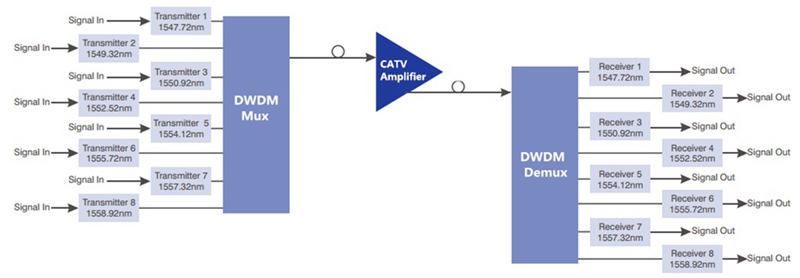
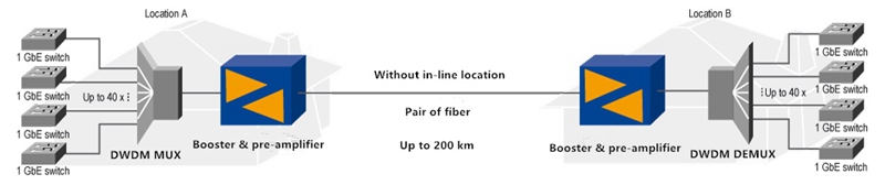
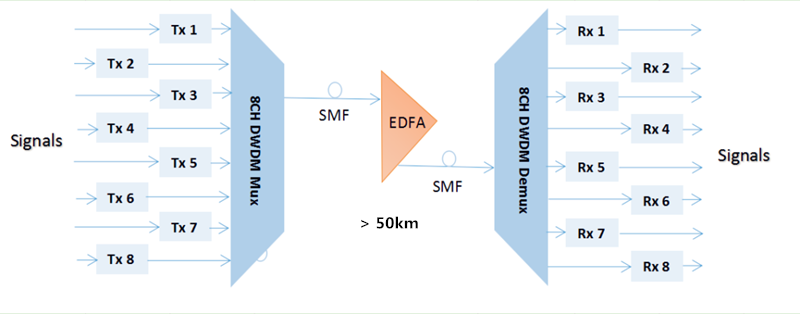
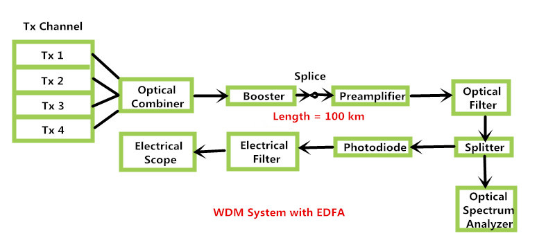
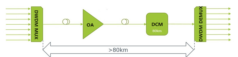
Unlike passive DWDM system, active DWDM system can be composed of fiber amplifier, DWDM Mux, DWDM transceiver, DCM module and OEO transponder, which can be also called transponder-based system. Due to its active feature, it is easier to manage and control the optical active DWDM network. Here offers the design of the active DWDM system for your reference.

Active DWDM

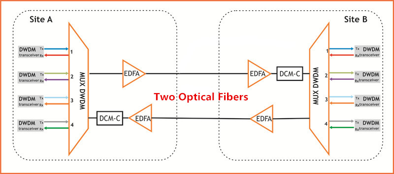
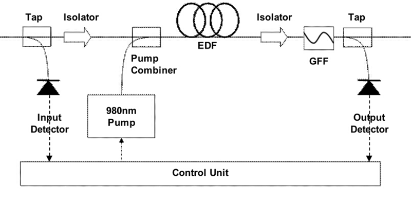
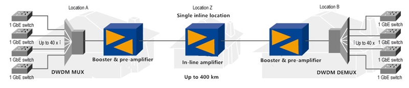
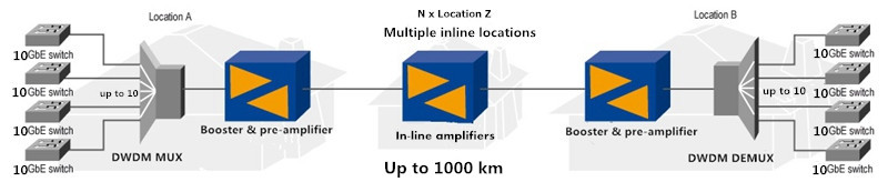
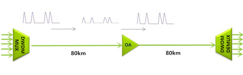
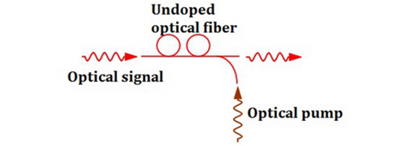
In the active DWDM system, the transponder usually utilizes short wave 850nm or long wave 1310nm to do the optical-electrical-optical (OEO) DWDM conversion. When the long distance is required in the active DWDM system, several EDFA fiber amplifiers will be inserted along the active DWDM link. What should be noted is that the active DWDM link can’t be extended infinitely, because the number of fiber amplifiers for an active DWDM link is limited to the optical cable type, the channel count, the data transmission rate of each channel, and permissible OSNR value, etc.

Furthermore, the chromatic dispersion occurring in the optical transmission also makes an influence on the transmission distance of the active DWDM link. Hence, when designing the active DWDM system, we should also take the permissible chromatic dispersion values of the link into consideration. If needed, we can insert the dispersion compensators (dcm modules) into the active DWDM link to enhance the optical signals for a longer transmission.

Passive DWDM vs Active DWDM System
It is well known that the passive DWDM system doesn’t need fiber amplifiers or dispersion compensators, which may saves you a lot of time and money. Meanwhile, it is also very easy to deploy due to the uncomplex installation. However, there are also several disadvantages of passive DWDM system. Firstly, the scalability is not so good as the active one. With the development of the passive DWDM system, more passive devices are required. Meanwhile, the passive DWDM system will be difficult to manage with the increasing of passive devices. What’s worse, if a wavelength or connection needs to be changed in the link, the only option is to take it out of link and disconnect the connection.

As for the active DWDM system, it can multiplex more wavelengths over a single fiber pair. Hence, more bandwidth can be provided by the active DWDM system. Furthermore, the active setups make the optical system management easier. And you can directly change the wavelengths or connections in the link without dropping connections. Finally, the active DWDM system is more scalable than the passive one, which makes more wavelengths to be multiplexed over the fiber. But one the other hand, there are also two main disadvantages of active DWDM system. One is the high cost of the active DWDM devices, and the other one is the complex installation.

In conclusion, the active DWDM system can offer greater capacity and higher scalablity, while the the passive DWDM system needs less cost and is easy to deploy. If the passive DWDM system meets your need, you’d better not to choose the active one as it will cost you very high. All in all, there is no the best, but the most suitable for your system. Just choosing the most suitable DWDM for your system according to what your network needs.

Friday, July 7, 2017

QSFP-40G-UNIV vs QSFP-40G-SWDM4

Nowadays, the demand for high bandwidth increases and footprints for data center expands dramatically, which makes the migration from 10G to 40G much more necessary than ever before. Under this condition, many enterprises are ongoing or imminent to upgrade their data center network infrastructures. To better cater for our users, two transceivers 40G UNIV and 40G SWDM4 QSFP using SWDM (Short Wavelength Division Multiplexing) technology are compared in the following text, which intends to offer a cost effective transceiver solution for 10G to 40G migration applications. As parallel multimode MPO fiber cabling is much more expensive than Duplex-LC fiber cabling, Duplex-LC fiber patch cords will be used in these two SWDM applications, as a cost saving cabling method.

40G Direct Port-to-Port Connection

QSFP 40G UNIV Transceiver for SWDM Application
QSFP 40G UNIV is a kind of pluggable optical transceiver that fitted with Duplex-LC connector and can work with both single-mode and multimode fiber patch cable, originally released by Arista. Hence, it is also referred to as 40G SMF&MMF transceiver or 40G QSFP universal transceiver. When working with singlemode fiber, the Arista QSFP 40G UNIV can support 40G connection with a reach of 500m; and over OM3/OM4, the transmission distance can be up to 150m. Furthermore, the Arista QSFP 40G UNIV is designed with four 10G channels for transmitting and receiving four individual 10G signals through a single Duplex-LC fiber patch cord, for achieving a total 40G connection, as shown in the following figure.

Arista QSFP 40G UNIV

How does the Arista QSFP 40G UNIV work for 40G connection? The answer is SWDM technology. With the help of SWDM, Arista QSFP 40G UNIV will multiplex four wavelengths 1270nm, 1290nm, 1310nm and 1330nm to transmit four 10G signals over the single Duplex-LC fiber patch cord. And when the aggregate 40G signal passes through the receiver end, it will be demultiplexed into four individual 10G signals again. As a result, an aggregate 40G signal can be transmitted through a single Duplex-LC fiber patch cord. In short, Arista 40G universal transceiver is a very good choice for 40G migration which can work with LC-duplex single-mode or multimode fiber, instead of high-cost parallel multimode MPO fiber cabling.

QSFP 40G SWDM4 Transceiver for SWDM Application
QSFP 40G SWDM4 is an updated optical transceiver that basically works with Duplex-LC fiber patch cord for short 40G fiber link. It has the same working principle that uses SWDM technology as the QSFP 40G UNIV one, but can perform better. How does it do this? Unlike QSFP 40G UNIV working with both single-mode and multimode fiber, the QSFP 40G SWDM4 is designed to work with multimode fiber, which can transmit a multiplexed 40G signal over wide band OM5 at lengths up to 440m. It can also work in multimode fiber OM3 and OM4 with a reach of 240m and 350m, separately. What’s more, the power dissipation of QSFP 40G SWDM4 can be as low as 1.5W* since SWDM technology can match 4x WDM optical architecture with 4x electrical interface.

Similar to the QSFP 40G UNIV transceiver, four different wavelengths, 850nm, 880nm, 910nm and 940nm are used in the QSFP 40G SWDM4 transceiver. To transmit a total 40G signal, these four wavelengths will be multiplexed to carry four individual 10G signals, be transmitted through the Duplex-LC multimode fiber patch cord and finally demultiplexed. To better understand the principle of QSFP 40G SWDM4 transceiver, you can learn the above figure that illustrates how does the QSFP 40G SWDM4 work for a short distance 40G fiber link.

40G SWDM4 Transceivers

QSFP-40G-UNIV vs QSFP-40G-SWDM4, Which One is Better?
After discussion, we can learn that both QSFP 40G UNIV and QSFP 40G SWDM4 transceivers enable network operators to grow the capacity of their networks without laying new fiber cabling. In view of the transmission distance, QSFP 40G SWDM4 transceiver working with OM5 supports a longer 40G fiber link than QSFP 40G UNIV with OM3/OM4, but a shorter 40G fiber link than QSFP 40G UNIV with single mode fiber cable. When taking fiber cabling infrastructure cost into consideration, OM5 cabling costs about 50% more than OM4 and singlemode fiber is also very expensive. Then which one should be selected? Just depending on your network needs, such as the fiber link distance, the budget, etc. To better know the differences between QSFP 40G UNIV and QSFP 40G SWDM4 transceivers, here offers a table that shows their detailed parameters.

Thursday, June 29, 2017

Time to Use CPAK Transceiver for 100G Network Deployment

Over the past few years, we gave a warm welcome to 100G network market, for meeting our ever-increasing demand. With the prosperous development of 100G optical technology, several 100G transceivers like CFP, CFP2, CFP4, QSFP28 have come out that we may be very familiar with. Except for these common 100G transceivers, CPAK transceiver also plays an important role in 100G network that would be a good choice if you need to deploy a 100G network. What’s the benefits of CPAK transceiver, compared to other 100G transceivers? Why it is an ideal solution to deploy 100G network with CPAK transceiver? Let’s talk about this topic.

Introduction to 100G CPAK Transceiver
CPAK transceiver module is a kind of hot-swappable I/O component for inserting into 100G Ethernet Port of Cisco switch and router, published in 2013 by Cisco. This kind of transceiver has generally 82 pins on its electrical interface, 40 of which are on the top row and 42 on the bottom row. While on its optical interface, there is a duplex SC or 24-fiber MPO connector. In contrast to other optical transceivers, 100G CPAK is distinctive, designed on the basis of complementary metal-oxide semiconductor (CMOS) photonics technology, which features the advantages of high optical integration, performance, power savings, and scalability.

CPAK transceiver has the greatest density and bandwidth but the lowest power consumption which is an ideal 100G solution for data center, enterprise and edge networks. To well serve 100G demand, it has several types like CPAK 100G SR10, CPAK 100G ER4L, CPAK 100G LR4 with different IEEE-standard optical interfaces that can support 100G connections with different distances. You can learn some common CPAK transceivers with different optical interfaces from the figure below.

100G CPAK transceiver consist of CPAK 100G SR10, CPAK 100G ER4L, CPAK 100G LR4, and etc.

Benefits of 100G CPAK Transceiver
To face the exploding demand of network bandwidth, 100G solution came into the market with high cost. Under this condition, experts turn to explore the high density but cost effective solution to make the 100G network commonly deployed. And the 100G CPAK transceiver is just the alternative to the existing 100G transceiver that has higher port density and power saving. Let’s learn the main benefits of this kind of 100G transceiver.

Firstly, 100G CPAK transceiver is designed on the basis of COMS technology which solves the limitation of optical interconnect technology. As we know, COMS photonics is a technology that can control the flow of photons in place of electrons by integrating multiple circuit components in a highly efficient design, and then printing entire circuits directly on silicon wafers to produce optical devices. Hence, the 100G CPAK transceiver utilizing COMS technology has a smaller footprint but higher port density, which enables extremely efficient, low-power optical circuits.

Secondly, CPAK transceiver is a 100G power saving and high density transceiver solution, addressing the existing 100G transceivers’ big physical size, excessive heat and power problems. Different from the existing 100G transceivers, CPAK transceiver is designed to decrease the space and power requirements by over 70 percent, while improving the port density and front-panel bandwidth up to 20 percent. It has great improvements in size, power consumption, density and bandwidth for facing the increasing need to scale data center and networking equipment.

Conclusion
CPAK transceiver is an economical choice to deploy 100G network which exceedingly solve the big size and excessive power problems in the existing 100G transceivers. Considering that, 100G CPAK transceiver modules like CPAK 100G SR10, CPAK 100G ER4L, CPAK 100G LR4 are available on the market, with very good price and quality assurance, for better serving 100G users.

Friday, June 9, 2017

Analysis of Power Budget and Link Distance in CWDM System

It can’t be denied that CWDM technology is a cost effective method to increase the capacity in the existing system, which can give different wavelengths to multiple optical signals and multiplex them for transmission through only one single fiber. Different from the DWDM system, the network using CWDM technology are deployed by passive components like passive CWDM Mux Demux, without the need of additional power, which makes CWDM system more commonly used. Do you also plan to build a CWDM system? If yes, you can check the following information for reference, which mainly analyzes the optical power budget in a CWDM system and calculates the CWDM link distance according to the power budget for smoothly deploying a CWDM system.

What’s Optical Power Budget?
Before deploying an optical network, it is very essential to calculate the optical power budget for better deployment. What’s optical power budget? It is just the amount of light available to make a successful fiber connection which can be calculated by analyzing the original output power of the transmitter and the required input power of the receiver. In details, we should firstly learn the optical power that is emitted by the source (also referred to Transmit Power) and the required power of the detector (also called Receiver Sensitivity). Using the first data to subtract the second one, you’ll get the data of the optical power budget which greatly determines the performance of the whole network link.

Here is the equation: Optical Power Budget = Transmit Power - Receiver Sensitivity.

How to Get the Optical Power Budget in a CWDM System?
To estimate the link distance supported by a CWDM system, the optical power budget should be calculated first, which can greatly determine the CWDM link distance. Here will show you a basic CWDM system under an ideal condition to clearly illustrate how to get the optical power budget. In this basic CWDM system, there is a optical transmitter which transmit power is -2 dBm and a optical receiver with -25 dBm receiver sensitivity. Hence, the optical power budget is 23 dB, as shown in the following equation.

Optical Power Budget = Tx Power - Rx Sensitivity = -2 dBm - (-25 dBm) = 23 dB

However, the mentioned CWDM system is just under an ideal condition without loss caused by the signal transmission. In a normal CWDM system, there are many components like passive CWDM Mux Demux, CWDM transceiver inserted. All these components cause insertion loss once they are inserted into the CWDM link. Therefore, when doing the optical power budget, all the loss should be taken into account for calculating the power budget exactly.

Here is more exact equation: Power Budget = Tx Power - Rx Sensitivity - Loss

To get the real power budget of a CWDM system, here offers a simple CWDM link which uses the -2 dBm optical transmitter, -25 dBm optical receiver and four passive CWDM Mux Demux with low insertion loss. Both the stable 4 channel CWDM Mux and stable 4 channel CWDM Demux in the link have 2.0 dB insertion loss, and other two are 8 channel ones feature 2.5dB insertion loss separately, as shown in the figure below. As a result, the total loss caused by the four passive CWDM Mux Demux is 9 dB, resulted from 2.5 dB + 2.0 dB+2.5 dB + 2.0 dB. Then we can get the total power budget, 14 dB. The calculation process is: Power Budget = Tx Power - Rx Sensitivity - Loss = -2 dBm - (-25 dBm) - 9 dB = 14 dB

Power Budget for CWDM Network

How to Calculate the Link Distance in the CWDM System?
After knowing the optical power budget, let’s calculate the link distance of the CWDM system according to the following equation: Link Distance = Optical Power Budget/Fiber Attenuation. As there may be some other power loss caused by the factors that we didn’t consider like fiber aging, temperature and poor splice, we often subtract 2 dB buffer from the total optical power budget. Meanwhile, the fiber attenuation is changeable according to the wavelength, usually varying from 0.2 to 0.35 dB/km. In this case, we’ll use 0.35 dB/km as a typical data. Then we can get the link distance is about 34 km. The calculation process is Link Distance = Optical Power Budget/Fiber Attenuation = (14 dB- 2 dB)/0.35 dB/km.

Conclusion
This paper intends to illustrate how to calculate the optical power budget and estimate the link distance of a CWDM system according to the optical power budget, which allows for better budget of deploying the CWDM system and eliminates the unwanted or unnecessary issues which may happen in the system deployment. Besides, if you want to make a cost effective CWDM system, you are suggested to buy CWDM components like cheap passive CWDM Mux Demux, CWDM transceivers from FS.COM, which are of good price and quality.

Monday, June 5, 2017

What Can CATV Systems Benefit from EDFA Optical Amplifiers?

As long-distance transmissions are always required in the CATV systems, it is very necessary to make the quality of visual and audio signals in high levels after the long transmissions, so that the performance of the CATV systems can be ensured. To serve this aim, the CATV EDFA optical amplifiers are come up with and widely used in the CATV systems. Why the EDFA optical amplifier is needed in CATV system? How does it work for the long CATV application? The following text will give you the answers and simply introduce two typical CATV EDFA amplifier applications for your reference.

What’s CATV EDFA Amplifier?
CATV EDFA is a kind of optical amplifier, most commonly used in the long-haul CATV system for boosting the damped CATV signals, with the aim of compensating the signal loss. Since it mostly works as booster optical amplifier in the CATV system, so that it can be also called CATV booster amplifier. By utilizing the CATV EDFA optical amplifier, the CATV signals can be enhanced to meet the system requirement and then be sent to the users. However, when the signal power is improved by the CATV EDFA, the noise existing in the transmission link would also boosted and some return loss would also occur at the same time. Considering that, it is very necessary to choose quality CATV EDFA optical amplifier for ensuring the performance of CATV system, even if it may be cost a little higher than common optical amplifier.

Why CATV EDFA Optical Amplifier is Used?
CATV is a multi-channel TV system transmitting visual and audio signals from digital or analog television and radio channel to many users via fiber or copper patch cable. As the signals should be finally separated by optical splitter to serve more than one users and many loss has occurred in the long transmission, the overall speed and quality of the CATV signals would become too weak to meet the receiver requirements. Under this condition, the CATV EDFA optical amplifier is very essential for CATV system with the function of amplifying CATV signals and giving high performance systems to the users.

How Does CATV EDFA Work for Long CATV Applications?
A long CATV system is always composed of head end, transmitter, receiver, CATV booster amplifier and optical splitter. When the system runs, the CATV signals are provided by the head end, and need to be split into several signals by the optical splitter to serve the users. When the signals pass through the optical splitter, the signal power would be in a very low level. Hence, the CATV EDFA optical amplifier should be deployed after the receiver to improve the signal power, and the users can finally receive quality signals.

http://www.chinacablesbuy.com/wp-content/uploads/2017/06/CATV-EDFA-Optical-Amplifier

From the figure above, we can learn a simple point-to-multipoint CATV network design as mentioned above. The CATV signals are provided by the RF combiner and should be connected with four receivers by the optical splitter. In order to compensating the signal loss caused by the optical splitter, CATV EDFA optical amplifier is required before sending the weak signals to the users.

Except for this simple kind of CATV network using CATV EDFA optical amplifier, here also offers a complex CATV network, as designed in the figure below. In this CATV network, the CATV EDFA optical amplifier is deploy behind the 8 channel DWDM Mux Demux to amplify the signals while the 8 channel DWDM Mux Demux allows for higher capacity transmission. Hence, a long CATV network with big capacity can be achieved.

 CATV EDFA Optical Amplifier with DWDM Mux

Conclusion
When deploying a long CATV system, we should pay attention to the loss caused by long transmission distance and CATV components. When the loss is very high, CATV EDFA optical amplifier would be an ideal device deployed in the long CATV system for improving the quality of CATV signals, so that the users can receive high speed and reliability of the services.

Thursday, June 1, 2017

EDFA Amplifiers for Building Long-haul DWDM Networks

Clearly different from the traditional repeater, the EDFA amplifier doesn’t need to convert the optical signals into electrical ones, then make the electrical amplification and finally convert the amplified electrical signals into amplified optical signals again. It is an optical amplifier that can directly enhance the optical signals without making additional conversion. By using the EDFA optical amplifier, the attenuated signal power can be amplified into strong signal level to meet the requirement of the long-haul applications, especially the long-haul DWDM networks. To better understand the function of EDFA amplifier, the following will mainly study the working principle of EDFA amplifier works and illustrate how to use it to build the long DWDM network.

What’s the Working Principle of EDFA Amplifier?
From the figure below, we can learn the basic configuration of the EDFA amplifier, mainly composed of a length of EDF (erbium doped fiber), a pump laser with 980 nm or 1480 nm, a pump combiner and a simple WDM system. When the attenuated signals around 1550 nm pass through an EDFA amplifier, a pump laser will be generated. Then the DWDM signals and pump laser will be combined by the pump combiner. When they come into the EDF together, the wavelengths of signals and pump laser will be multiplexed and the interaction with the doping ions would enhance the signal power into high level. Thereby, a longer DWDM transmission can be reached.

EDFA Amplifier Configuration

How to Use EDFA Amplifier for Long DWDM network?
In a long DWDM network, the EDFA amplifier can be put in three different places with different aims. Firstly, we can put it in the transmitter side of the DWDM link to offer high input signal power, so that the DWDM fiber link can be extended. If the EDFA amplifier is deployed in this place, we can also call it EDFA optical booster amplifier. Secondly, we can also place the EDFA amplifier in the receiver side of the DWDM link as optical preamplifier, hence the output signal power can be boosted to meet the necessary receiver level. Finally, when the fiber loss in the transmission process is too high to support the long DWDM network, we can deploy the EDFA amplifier in any intermediate point along the long fiber link to compensate the fiber loss. And this time, we can call it EDFA optical in-line amplifier.

Analysis of Practical Long DWDM Cases with EDFA Amplifiers
Case One: in this case, EDFA optical booster amplifiers are deployed at both transmitter sides of the dual-way DWDM links. We can learn it from the figure below. Two 40 channel DWDM Mux Demux are deployed to multiplex 40 1G signals. Then the two integrated 40G signals from both sides are enhanced by the booster amplifier and can be transmitted up to 170 km over each single fiber.

EDFA Optical Booster Amplifier

Case Two: as shown in the following figure, except for the booster amplifiers, EDFA optical optical preamplifiers are also placed at both receiver sides of the dual-way DWDM links. By adding the optical preamplifiers to the CWDM link, the transmission distance is finally extended from 170 km to 200 km.

EDFA Optical Preamplifier

Case Three: it is highly noted from the following figure that the DWDM transmission distance can be up to 400 km. How to achieve this? Just putting the EDFA amplifiers in the three places mentioned above. As deployed in the figure, a pair of EDFA optical booster amplifiers, optical preamplifiers and optical in-line amplifiers are used for the 400km transmission.

EDFA Optical in-line Amplifier

Case Four: If the distance of 400 km still cannot meet our requirement, we can set up more repeater sites to place other optical in-line amplifiers. At present, using these three kinds of EDFA amplifiers already enables 100Gbps bandwidth for realizing up to 1000 km in a point-to-point connection, as shown in the figure below.

EDFA Amplifiers for 100G 1000km Tranmission

Conclusion
When designing a long-haul DWDM network for transmitting big data, EDFA amplifier is an ideal solution for current and future optical system which should be taken into consideration. It can be deployed at the transmitter side, the receiver side and any intermediate point along the DWDM long fiber link, as optical preamplifier, booster amplifier and in-line amplifier, for enhancing the signal power, thereby a long-haul transmission can be deployed.

Friday, May 26, 2017

Why Not Build a 10G CWDM Network for Higher Capacity?

Although the 40G and 100G technologies develop vigorously recent years to meet the increasing need of higher capacity, they are still not widely accepted and applied due to high deploying cost. Under this case, choosing to build a 10G network is always the first choice for most users. But except upgrading our system, what else can we do when the 10G network can’t offer enough capacity? To address this issue, telcom engineers and researchers suggest that we can deploy the 10G CWDM networks. With use of CWDM optical multiplexer, this solution offers a highly cost effective method to gain more capacity on the basis of 10G network. Let’s study the benefits of 10G CWDM network and its two basic common network infrastructures in details.

What Can We Benefit from 10G CWDM Network?
In contrast to 10G DWDM network, 10G CWDM network can neither offer so high data capacity nor transmit the signals so long. But on the other hand, 10G CWDM network is an easier-to-deploy and less expensive solution that can well serve for a wide range of optical applications. Let’s study the main benefits of 10G CWDM networks.

  • It is possible to add connections for transmitting more data in 10G network, which makes the whole network load increasing from 10G to 40G or 100G possible.
  • CWDM Mux Demux is the key component of 10G CWDM network. As a passive component, it doesn’t require extra power, which is an ideal option for deploying 10G CWDM network.
  • Instead of upgrading system, deploying 10G CWDM network to get more capacity can saves a lot of money due to the economical 10G hardware and cheap passive CWDM Mux Demux.

Understanding Common 10G CWDM Network Infrastructures
10G CWDM system is a passive optical network, which supports 10G transmission with any protocol over the optical link, as long as the 10G signals are at the specific CWDM wavelengths. At present, there are two common CWDM network infrastructures. One is 10G CWDM point-to-point network, and the other is 10G CWDM ring network. The following will introduce the two common infrastructures in details.

10G CWDM Point-to-Point Network: it is the simplest network infrastructure of the CWDM networks. As shown in the following figure, there are two passive CWDM Mux Demux deployed in the 10G network that offers 8 channels to multiplex the signals from 8 different optical fiber link into an integrated signal. Thereby, the signal can be transmit through only one fiber, which means there are 7 virtual fiber created with higher capacity for transmitting more data. As for the cheap passive CWDM Mux Demux, it can be available at very good price that costs less than upgrading the system from 10G to 40G or 100G. Undoubtedly, deploying a 10G CWDM point-to-point network is very economical solution for higher capacity.

10G CWDM Point-to-Point Network with CWDM Mux Demux

10G CWDM Ring Network: it is deployed on the basis of 10G CWDM point-to-point network. Compared to point-to-point network, the ring network is much more complex that needs other optical CWDM components like CWDM OADM. By adding CWDM OADM, two or more point-to-point network can be connected together, which can finally achieve a 10G CWDM ring network. To better understand how does the 10G CWDM ring network work, here offer a figure that shows four buildings are connected by several 8 channels CWDM Mux Demux and CWDM OADM for your reference.

10G CWDM Ring Network with CWDM Mux Demux

Conclusion
Unlike upgrading the network from 10G to 40G or 100G, building a 10G CWDM network doesn’t requires changing all the network equipment which may cost highly. It only need CWDM transceiver and CWDM Mux Demux to be deployed in the original 10G network. For a complex 10G CWDM network, additional optical equipment like CWDM OADM are required. If you come across the capacity-hungry issue, building a 10G CWDM network would be a nice option for higher capacity.

Wednesday, May 24, 2017

How to Extend Your Network Transmission Distance?

To face the need for long-haul, high-capacity transmission, experts come up with several DWDM projects including DWDM Mux Demux, EDFA amplifier (erbium-doped fiber amplifier) and DCM module (dispersion compensation module) to expand network capacity and enhance the signal power, which can greatly extend the optical network reach. Do you have the need to deploy a longer fiber optical transmission link? If yes, you can just build a DWDM system with the DWDM projects mentioned above. This paper will introduce three solutions that utilize these DWDM components to extend the optical network transmission distance. Hope these DWDM solutions would be useful for you.

Using DWDM Mux Demux for Long Transmission up to 50 km
DWDM technology plays an important role in building long-haul transmission system, which enables multiple signals with different wavelengths to be transmitted through only one single fiber. To build a long system with DWDM technology, the DWDM Mux Demux is an indispensable component that features low insertion loss and polarization-dependent loss. By using the DWDM Mux Demux in your network, the signal transmission distance can be extended to up to 50 km. To better know the advantage of DWDM Mux Demux, here offers an example that uses two 8 channel DWDM Mux Demux for extending the optical fiber link.

8 channel DWDM Mux Demux for Long transmission

From the figure, we can learn that at the transmit side, eight kinds of signals from different fiber links are multiplexed into an integrated signal by the 8 channel DWDM Mux. Then the integrated signal is transmitted over the single mode fiber (SMF) and the maximum transmission distance can be up to 50 km. At the receiver side, the signal will be demultiplexed into individual signals with their original wavelengths by the 8 channel DWDM Demux and then transmitted to another eight different fiber links. Just by using the DWDM Mux Demux, a 50km long-haul transmission can be simply achieved.

Adding EDFA Amplifier for Transmission Longer Than 50 km
As we know, the longer the transmission distance is, the higher the fiber loss will be. Hence, except for the DWDM Mux Demux, you are suggested to add an EDFA amplifier to the long fiber link if the transmission distance is longer than 50 km. What’s the function of EDFA amplifier? It is mainly designed to amplify the signal power, which enables longer transmission. As shown in the following figure, you can learn that the only difference is the EDFA amplifier in the SMF, compared to the first solution.

EDFA and 8 channel DWDM Mux Demux for Long transmission

When the integrated signal multiplexed by the 8 channel DWDM Demux is transmitted over the SMF, it would become too weak in the transmission process to be transmitted. Then the EDFA amplifier should be placed there to boost the signal power, supporting the transmission longer than 50 km. Once the long transmission is realized, the signal will be also split by the 8 channel DWDM Demux, like the first solution. In short, DWDM Mux Demux and EDFA amplifier are highly suggested if you want to deploy a DWDM system longer than 50 km.

Adding DCM Module for Transmission up to 200 km
With the use of EDFA amplifier, the DWDM fiber link can be extended to 200 km. However, the signal quality is always unsatisfied due to the optical dispersion in long transmission, especially in CATV systems. To meet high requirements of the signal quality in these long transmission systems, an additional optical component, DCM module are needed in the long fiber link, as deployed in the figure below.

DCM, EDFA and 8 channel DWDM Mux Demux for Long transmission

From the figure, we can learn it is a long-haul point-to-multipoint CATV system. To extend the transmission distance, 8 channel DWDM Mux Demux, EDFA amplifier are used. Except for that, a DCM module is added to enhance the skew signal for ensuring the whole transmission quality. With the use of DCM module, the accumulated chromatic dispersion issue is solved, without dropping and regenerating the wavelengths on the long fiber link. Thereby, a high-performance 200km system can be reached.

Conclusion
DWDM projects including DWDM Mux Demux, EDFA amplifier and DCM module are key optical components to support long-haul transmission systems. If you want to deploy a long transmission system up to 50 km, then the DWDM Mux Demux is needed. For transmission longer than 50 km, both the DWDM Mux Demux and EDFA amplifier are required for boost the signal power. But once the transmission distance is about 200 km, you should additionally add the DCM module to enhance the signal quality.

Friday, May 19, 2017

Whether to Use EDFA Amplifier in Long WDM System Or Not?

Currently, utilizing WDM technology to deploy the optical network has received widespread attentions, which enables higher capacity for data transmission. However, the technology is also limited by the transmission distance. When deploying a long WDM system, the signal power would still become weak due to the fiber loss. In order to address the issue, using EDFA amplifier to directly enhance the WDM signals would be a good choice for current and future optical network needs. The optical network combining WDM technology and EDFA module together can transmit multiple signals over the same fiber, at lengths up to a few hundred kilometers or even transoceanic distances. To better know how does EDFA amplifier work in the long WDM system, let’s learn the EDFA amplifier knowledge and analyze the performance of WDM system bonding with the EDFA module.

Introduction to EDFA Amplifier

EDFA amplifier, also referred to as erbium-doped fiber amplifier, is basically composed of a length of Erbium-doped fiber (EDF), a pump laser, and a WDM combiner. When it works, the pump laser with 980 nm or 1480 nm and the input signal around 1550 nm can be combined by the WDM combiner, then transmitted and multiplexed into the Erbium-doped fiber for signal amplification. The pump energy can be transmitted in the same direction as the signal (forward pumping), or the opposite direction to the signal (backward pumping), or both direction together. And the pump laser can also using 980 nm or 1480 nm, or both. Taking the cost, reliability and power consumption into account, the forward pumping configuration with 980nm pump laser EDFA amplifier is always the first choice to enhance the signals for a long WDM system.

Analysis of WDM Network Without EDFA Amplifier

Before analyzing WDM network deployed with EDFA amplifier, it is necessary to know the basic configuration of an original WDM network, as shown in the figure below. We can learn that four signals from different channels are combined by the optical combiner. And then, the integrated signals are transmitted through an optical fiber. Thirdly, the signals are split into two parts by the splitter. One part passes through the optical spectrum analyzer for analyzing signals, and the other one goes through the photo detector to be converted into electrical signal and then be observed by the electrical filter and scope. However, in the process, the signal power gets highly attenuated after being transmitting at long distance.

WDM System Without EDFA

Analysis of WDM Network Using EDFA Amplifier

By using the EDFA amplifier, we can easily overcome the attenuation of long WDM network. From the following figure, we can learn that EDFA amplifiers act as booster amplifier and pre-amplifier to enhance the signal, so that system will no longer suffer from losses or attenuation. Therefore, if you need to deploy a long WDM system, it is highly recommended to deploy the EDFA amplifiers in the system that features flat gain over a large dynamic gain range, low noise, high saturation output power and stable operation with excellent transient suppression. It is an undoubtedly ideal solution with reliable performance and relatively low cost to extend the WDM network transmission distance.

WDM System with EDFA

Conclusion

It is well know that the signal power would be greatly attenuated when the transmission distance is long enough. Hence, when deploying a long WDM network, it is definitely necessary to use the EDFA amplifier to enhance the signal strength, allowing for the long transmission distance. As a preferable option, the EDFA amplifier with very low noise is relatively insensitive to signal polarization and easy to realize signal amplification.

Wednesday, May 17, 2017

EDFA vs Raman Optical Amplifier

Although the fiber loss limits the transmission distance, the need for longer fiber optical transmission link seems never ending. In the pursuit of progress, several kinds of optical amplifiers are published to enhance the signals. Hence, longer fiber optical transmission link with big capacity and fast transmission rate can be achieved. As the EDFA and Raman amplifiers are the two main options for optical signal amplification. which one should be used when designing long fiber optical network? What are the differences of the two optical amplifiers? Which one would perform better to achieve the long fiber optical link? And which one is more cost effective? Let’s talk about this topics.

What’s EDFA Amplifier?
EDFA (Erbium-doped Fiber Amplifier), firstly invented in 1987 for commercial use, is the most deployed optical amplifier in the DWDM system that uses the Erbium-doped fiber as optical amplification medium to directly enhance the signals. It enables instantaneous amplification for signals with multiple wavelengths, basically within two bands. One is the Conventional, or C-band, approximately from 1525 nm to 1565 nm, and the other is the Long, or L-band, approximately from 1570 nm to 1610 nm. Meanwhile, it has two commonly used pumping bands, 980 nm and 1480 nm. The 980nm band has a higher absorption cross-section usually used in low-noise application, while 1480nm band has a lower but broader absorption cross-section that is generally used for higher power amplifiers.

The following figure detailedly illustrates how the EDFA amplifier enhance the signals. When the EDFA amplifier works, it offers a pump laser with 980 nm or 1480 nm. Once the pump laser and the input signals pass through the coupler, they will be multiplexed over the Erbium-doped fiber. Through the interaction with the doping ions, the signal amplification can be finally achieved. This all-optical amplifier not only greatly lowers the cost but highly improves the efficiency for optical signal amplification. In short, the EDFA amplifier is a milestone in the history of fiber optics that can directly amplify signals with multiple wavelengths over one fiber, instead of optical-electrical-optical signal amplification.

EDFA Amplifier Principle

What’s Raman Amplifier?
As the limitations of EDFA amplifier working band and bandwidth became more and more obvious, Raman amplifier was put forward as an advanced optical amplifier that enhances the signals by stimulated Raman scattering. To meet the future-proof network needs, it can provide gain at any wavelength. At present, two kinds of Raman amplifiers are available on the market. One is lumped Raman amplifier that always uses the DCF (dispersion compensation fiber) or high nonlinear fiber as gain medium. Its gain fiber is relatively short, generally within 10 km. The other one is distributed Raman amplifier. Its gain medium is common fiber, which is much longer, generally dozens of kilometers.

When the Raman amplifier is working, the pump laser may be coupled into the transmission fiber in the same direction as the signal (co-directional pumping), in the opposite direction (contra-directional pumping) or in both directions. Then the signals and pump laser will be nonlinearly interacted within the optical fiber for signal amplification. In general, the contra-directional pumping is more common as the transfer of noise from the pump to the signal is reduced, as shown in the following figure.

Raman Amplifier Principle

EDFA vs Raman Optical Amplifier: Which One Wins?
After knowing the basic information of EDFA and Raman optical amplifiers, you must consider that the Raman amplifier performs better for two main reasons. Firstly, it has a wide band, while the band of EDFA is only from 1525 nm to 1565 nm and 1570 nm to 1610 nm. Secondly, it enables distributed amplification within the transmission fiber. As the transmission fiber is used as gain medium in the Raman amplifier, it can increase the length of spans between the amplifiers and regeneration sites. Except for the two advantages mentioned above, Raman amplifier can be also used to extend EDFA.

However, if the Raman amplifier is a better option, why there are still so many users choosing the EDFA amplifiers? Compared with Raman amplifier, EDFA amplifier also features many advantages, such as, low cost, high pump power utilization, high energy conversion efficiency, good gain stability and high gain with little cross-talk. Here offers a table that shows the differences between EDFA and Raman optical amplifiers for your reference.


Considering that both EDFA and Raman optical amplifiers have their own advantages, which one should be used for enhancing signals, EDFA amplifier, Raman amplifier or both? It strictly depends on the requirement of your fiber optical link. You should just take the characteristics of your fiber optical link like length, fiber type, attenuation, and channel count into account for network design. When the EDFA amplifier meets the need, you don’t need the Raman amplifier as the Raman amplifier will cost you more.

Tuesday, May 9, 2017

How to Enhance the Optical Signals for a Long DWDM System?

As we know, the longer the optical transmission distance is, the weaker the optical signals will be. For a long DWDM system, this phenomenon easily causes transmission error or even failure. Under this case, what can we do for a smooth, long DWDM system? The answer is optical signal enhancement. Only by enhancing the optical signals, can the DWDM transmission distance be extended. In this post, we are going to learn two effective solutions, optical amplifier (OA) and dispersion compensating module (DCM) to enhance the signals, for making a smooth, long DWDM system.

Optical Amplifier Solution
We used to utilize repeater to enhance the signals in fiber optics, which should firstly convert the optical signals into an electrical one, amplify the electrical signals, and then convert the electrical signals into an optical one again. Finally, you can get the enhanced optical signals. However, this method of enhancing signals can not only cause more signal loss, but also add unwanted noises in the actual signal. Taking these issues into account, the optical amplifier is more recommendable.

An optical amplifier is a device that enables direct optical signal enhancement or amplification. Its working principle is not so complicated as that of the repeater, while its performance is much higher. From the following figure, we can learn that the original reach of the DWDM system is limited to 80 km due to the signal loss. But with the optical amplifier, the signals are enhanced and the reach can be extended to 160 km. It is really an ideal option to enhance the signals for a long DWDM system.

Optical Amplifier (OA)
At present, there are mainly three major kinds of optical amplifiers, Semiconductor Optical Amplifier (SOA), Doper Fiber Amplifier (DFA), and Raman Amplifier (RA).

Semiconductor Optical Amplifier: as its name implies, the semiconductor in a SOA is used to offer the gain medium. This kind of optical amplifier has a similar structure to the FP laser diode. However, it is designed with anti-reflection elements at the end face that can greatly reduce the end face reflection. Meanwhile, the SOA features small package and low cost that suits for most users to enhance the optical signals.

Doper Fiber Amplifier: in a DFA, the doped optical fiber acts as the gain medium for signal amplification. When the DFA works, the signal to be amplified and a pump laser are multiplexed into the doped fiber. And then the signal is amplified through interaction with the doping ions. The most common DFA is the Erbium Doped Fiber Amplifier (EDFA). Its gain medium is a optical fiber doped with trivalent erbium ions that always enhances the signals near 1550nm wavelength. Undoubtedly, the EDFA is a great choice to enhance the optical signals.

Raman Amplifier: different from the SOA and DFA, the signal in a RA is amplified through the nonlinear interaction between the signal and a pump laser within an optical fiber. In details, two kinds, distributed and lumped Raman amplifier (DRA and LRA) are available on the market. The distributed one multiplexes the pump wavelength with signal wavelength through the transmission fiber to enhance the signals, while the amplification of the lumped one is provided by a dedicated, shorter length of fiber.

Dispersion Compensating Solution
Apart from signal amplification, we can also use dispersion compensation to enhance the optical signals. Once the dispersion occurs, the signal will be tended to skew due to the different frequencies, which has a negative effect on the quality of signal transmission. At that moment, we use the dispersion compensating module to enhance the skew signal, for achieving a longer transmission distance. As shown in the figure below, the DWDM system is extended to longer than 80 km with the use of 80km passive dispersion compensating module.

Dispersion Compensating Module (DCM)

The dispersion compensation module is an important component for a long fiber optical link. It typically connects to the mid-stage of an OA like EDFA, in the long haul transmission system. Except for the 80km DCM mentioned above, FS.COM also provides other DCM modules that allow long transmission distance extension. The compensation distances can range from 10km to 140 km, as shown in the following table.

Dispersion Compensation Module

The optical amplifier has the ability to directly boost the weak signal, while the dispersion compensation module can reshape the deformed signal and offer a long compensation distance. Considering that the signal strength would become weak as the transmission distance increases, using the optical amplifier and dispersion compensation module to enhance the signals is very necessary when building a long DWDM system.

Conclusion
The optical amplifier has the ability to directly boost the weak signal, while the dispersion compensation module can reshape the deformed signal and offer a long compensation distance. Considering that the signal strength would become weak as the transmission distance increases, using the optical amplifier and dispersion compensation module to enhance the signals is very necessary when building a long DWDM system.

Thursday, May 4, 2017

Economical Solutions for 10G to 40G Connection

With the accelerated development of optical network, there exist more and more capacity-hungry applications in 10G networks today. To solve this problem, experts put forward the 10G to 40G connection as an ideal solution. However, due to the high migration cost, we are prevented from making the migration. Do you also meet this issue? In this paper, it will offer several solutions for making 10G to 40G connections with less cost. Hope you can find one that suits your network.

10G to 40G Connection

Economical Solutions for 10G to 40G Short Connection
How to make a short link between 10G and 40G switches? You can choose the 40GBASE-SR4 QSFP+ module that supports the 40G network at length up to 150 m. Meanwhile, four 10GBASE-SR SFP+ modules are required. So is the MTP-LC harness cable for connecting QSFP+ and four SFP+ modules. In details, FS.COM offers OM3 MTP-LC harness cable supporting 40G connection up to 100 m and OM4 up to150 m. All these equipment mentioned above are available at FS.COM with good prices. For the details, you can learn from the following table.


http://www.chinacablesbuy.com/wp-content/uploads/2017/05/Economical-Solutions-for-10G-to-40G-Short-Connection.jpg

If the link distance is longer than 150 m in your network, 40GBASE-CSR4 QSFP+ module may be a better choice. It can transmit the 40G signals longer, up to 400 m. As for the fiber patch cable, you can still chosse OM3 or OM4 MTP-LC harness cable. In general, the OM3 provided by FS.COM enables the connection up to 300 m, while OM4 up to 400 m. When making a short 10G to 40G migration, you can just choose FS.COM as an ideal fiber optical manufacturer. It offers all the equipment your network needs, including 10G and 40G switches, SFP+ and QSFP+ module and MTP-LC patch cable.

Economical Solutions for 10G to 40G Long Connection
Do you need to make a long 10G to 40G migration? FS.COM also offers several cost effective solutions. For example, up to 1km, 10km, 40km or even 80km 10G to 40G connection solutions. Let’s talk about the detail information of these solutions.

Spending Less for up to 40km 10G to 40G Connection


You can use the 40GBASE-PLRL4 QSFP+ and 10GBASE-LR SFP+ modules to support the 10G to 40G migration up to 1 km. The 40GBASE-LRL4 QSFP+ is also a good choice. As for the fiber patch cable, you can choose the 8 fibers single mode MTP-LC harness cable. Once the distance is longer than 1 km, your are suggested to use the 40GBASE-LR4 QSFP+ and 40GBASE-PLR4 QSFP+ modules. These two kinds of fiber transceiver modules enable the connection at lengths up to 10 km. It the link distance is up to 40 km, then you can use the 40GBASE-ER4 QSFP+ module. Here are the related equipment offered by FS.COM.

Economical Solutions for 10G to 40G Long Connection

Spending Less for up to 80km 10G to 40G Connection


Have you ever felt puzzled about whether the 10G to 40G connection can be extended to 80 km? Here you’ll find the answer is yes. How to deploy 80km 10G to 40G connection? You should add the extra equipment, including two DWDM Mux Demux, two WDM transponder OEO (Optical-Electrical-Optical) repeaters and several DWDM SFP+ modules, to your network.

In order to make a smooth 80km 10G to 40G migration, we should add the WDM transponder OEO repeater into the 10G to 40G link. It can not only act as fiber repeater for long distance transmission, but also CWDM/DWDM optical wavelength converter. When the 10G signals pass through the WDM transponder OEO repeater, it will be converted into several DWDM singals. Then you should use the DWDM Mux Demux to multiplex, transmit and demultiplex them. And finally another WDM transponder OEO repeater is required to convert the DWDM singals into 10G signals again. Hence, you can finally achieve the up to 80km 10G to 40G connection. As for the equipment the network requires, you can also order them from FS.COM with good prices.

Spending Less for up to 80km 10G to 40G Connection

Conclusion
FS.COM is an ideal fiber optical manufacturer that offers very cost effective solutions for 10G to 40G connection. These solution can support not only the short 10G to 40G migration at lengths up to 400 m, but also the long migration with reach 1km, 10km or even up to 40km. Moreover, if you want to extend the 10G to 40G connection up to 80 km, you can order the extra equipment like DWDM Mux Demux, WDM transponder OEO repeaters and DWDM SFP+ modules from FS.COM with good price. All the equipment mentioned above have been tested to assure 100% compatibility.

Original source: http://www.chinacablesbuy.com/economical-solutions-for-10g-to-40g-connection.html

Friday, April 28, 2017

Can the Hybrid CWDM-DWDM System Work for Higher Capacity?

When facing the capacity-hungry issue, have you ever hesitated over which WDM system should be choose? As the CWDM system is a more economical solution for limited expanding capacity while the expensive DWDM solution enables much higher capacity, which one should be chose is really a tough decision. In order to solve the issue, can we deploy a Hybrid CWDM-DWDM system, for not choosing a wrong solution to increase the network capacity? Thereby, both the bandwidth shortage with CWDM solution or the potential bankruptcy with DWDM solution can be avoided. Let’s seeking the answer.

Can the Hybrid CWDM-DWDM System Work?
Can the Hybrid CWDM-DWDM system work for higher network capacity? The answer is yes. In fact, it is an ideal solution for boosting the network capacity, which is designed with merging DWDM and CWDM traffic seamlessly at the optical layer, taking full use of the WDM technology. In a hybrid CWDM-DWDM system, more channels can be added to deal with the limited capacity and reach in a CWDM system. That’s to say, the hybrid CWDM-DWDM system utilizes the DWDM technology to empower CWDM system, by integrating CWDM and DWDM equipment, which offers true pay-as-you-grow capacity growth and investment protection.

In short, the hybrid CWDM-DWDM system is a simple, plug-and-play option that enables more DWDM channels interleaved with the existing CWDM channels, for transmitting more data signals. It gets the utmost out of CWDM and DWDM technologies in a single system that greatly reduces the cost, simplifies the installation and keeps the system flexibility for bigger network capacity.

How to Build a Hybrid CWDM-DWDM System?
In general, a normal complete optical connection can be simply done by using a length of fiber patch cable to connect two fiber transceivers and then separately inserting the two transceivers into the ports of two switches. While in a hybrid CWDM-DWDM system, both the CWDM Mux Demux and DWDM Mux Demux should be added offering multiple channels to multiplex and demultiplex the signals. Here offers a typical 44 channel hybrid CWDM-DWDM system information for your reference.

44 Channel Hybrid CWDM-DWDM System
From the figure, we can learn that the original CWDM system uses two 8 channel CWDM Mux Demux with wavelengths from 1470 nm to 1610 nm (20nm channel spacing). In order to add more channels for transmitting larger data signals, two pairs of DWDM multi-channel Mux/Demux are deployed separately under the pass band of the existing CWDM filters. In principle, deploying the DWDM multi-channel Mux/Demux in the 1530nm channel can create 25 100 GHz spaced DWDM channels. However, only 19 DWDM channels circled in the following figure are suitable to be added in the hybrid CWDM-DWDM system. It is also the same to the 1550 channel. Hence, this hybrid CWDM-DWDM system totally offers 6 CWDM channels and 38 DWDM channels with less deployment cost but easier installation.

DWDM Channels in Hybrid CWDM-DWDM System

Conclusion
If you come across the capacity-hungry issue and can’t make the decision about which WDM system should be choose for increasing your network capacity, you are highly recommended to deploy a hybrid CWDM-DWDM system. As an economical and future-proofing solution, the hybrid CWDM-DWDM system can completely deal with the issue of bandwidth shortage when building a CWDM system and avoid the potential bankruptcy for a DWDM system. You can just deploy a CWDM system first. Once the capacity the CWDM system offers can’t meet your requirement, you can add DWDM equipment in for more channels to transmit signals. All in all, the hybrid CWDM-DWDM system is an ideal choice that not only costs less for deployment but keeps the flexibility to increase the network capacity.

Tuesday, April 25, 2017

Dual-Fiber or Single-Fiber CWDM Mux Demux for Higher Capacity Need?

What would you do if your network capacity can not meet your requirement? Will you put more fibers or update your system? In fact, these two methods are not very recommendable. Why? As your fiber cabling infrastructure is limited for adding fibers and high cost is required for upgrading system, these two methods are unworkable or too expensive. Under this condition, using a pair of CWDM Mux Demux to build a CWDM system with higher capacity is highly recommended. The CWDM Mux Demux is regarded as a key component for a CWDM system, as shown below. It can be simply divided into two types, dual-fiber and single-fiber CWDM Mux Demux. To meet the higher capacity need of your system, this post will mainly introduce the basic knowledge of the dual-fiber and single-fiber CWDM Mux Demux and guide you find a suitable fiber optic Mux Demux for building your CWDM system.

CWDM Mux Demux for Connecting Cisco Nexus 9396PX and FS S5850-3252Q

Dual-Fiber CWDM Mux Demux
Dual-Fiber CWDM Mux Demux is a passive device multiplexing and demultiplexing the wavelengths for expanding network capacity, which must work in pairs for bidirectional transmission over dual fiber. It enables up to 18 channels for transmitting and receiving 18 kinds of signals, with the wavelengths from 1270 nm to 1610 nm. The CWDM transceiver inserted into the fiber optic Mux port should have the same wavelength as that of Mux port to finish the signal transmission. For instance, the two reliable 4 channel CWDM Mux Demux showed below use four wavelengths, 1510 nm, 1530 nm, 1550 nm and 1570 nm, their corresponding CWDM transceivers also features the same wavelengths.

Dual-Fiber CWDM Mux Demux

When the connection above works, the left 4 channel dual-fiber CWDM Mux Demux uses 1510 nm, 1530 nm, 1550 nm and 1570 nm for transmitting 4 kinds of signals through the first fiber, while the right 4 channel dual-fiber CWDM Mux Demux features 1510 nm, 1530 nm, 1550 nm and 1570 nm for receiving the signals. On the other hand, the transmission from the right to left use the same wavelengths to carry another 4 signals through the second fiber, finally achieving the bidirectional signal transmission.

Single-Fiber CWDM Mux Demux
Single-fiber CWDM Mux Demux should be also used in pairs. One multiplexes the several signals, transmits them through a single fiber together, while another one at the opposite side of the fiber demultiplexes the integrated signals. Considering that the single-fiber CWDM Mux Demux transmitting and receiving the integrated signals through the same fiber, the wavelengths for RX and TX of the same port on the Single-fiber CWDM Mux Demux should be different. Hence, if the 4 channel single-fiber CWDM Mux Demux is used for CWDM system, 8 wavelengths are required, the twice time as that of the dual-fiber one.

Single-Fiber CWDM Mux Demux

The working principle of single-fiber CWDM Mux Demux is more complicated, compared to the dual-fiber one. As shown in the figure above, the transmission from the left to right uses 1470 nm, 1510 nm, 1550 nm and 1590 nm to multiplex the signals, transmit them through the single fiber, and using the same four wavelengths to demultiplex the signals, while the opposite transmission carries signals with 1490 nm, 1530 nm, 1570 nm and 1610 nm over the same fiber. As for the wavelength of the transceiver, it should use the same wavelength as TX of the port on the CWDM Mux Demux. For example, when the port of a single-fiber CWDM Mux Demux has 1470 nm for TX and 1490 nm for RX, then a 1470nm CWDM transceiver should be inserted.

Dual-Fiber vs. Single-Fiber CWDM Mux Demux
We always consider whether an item is worth buying according to its performance and cost. In view of the performance, the single-fiber CWDM Mux Demux can carry signals through only one fiber supporting fast speed transmission and saving the fiber resource, while the dual-fiber one requires two fibers for transmission with a higher reliability. Besides, using single-fiber CWDM Mux Demux can be easier to install. In view of the cost, the single-fiber CWDM Mux Demux is much more expensive than the dual-fiber. And the simplex fiber cable also costs higher than duplex fiber cable. Thereby, the whole cost for building single-fiber CWDM system must be much more higher. Like the two sides of the same coin, both the dual-fiber and single-fiber CWDM Mux Demux have their own advantages and disadvantages. Which one you should choose just depends on your system needs and your budget for building the CWDM system.

Friday, April 21, 2017

Choose the Right SFP+ Transceivers for CWDM Mux Demux

Nowadays, CWDM technology is very popularly used as a easy and economical way to extend the network capacity by carrying several signals with different wavelengths through a signal fiber. If your network capacity is not enough for your daily use, deploying a CWDM system is an ideal choice for you. As the CWDM Mux Demux should be finally linked with the switches in a completed CWDM system, the fiber patch cable and 10G CWDM SFP+ transceiver are required to finish the whole CWDM link. Hence, this paper will mainly introduce the CWDM Mux Demux and choose the right CWDM SFP+ transceivers for the CWDM Mux Demux, which may be helpful for you to fast build a CWDM system.

CWDM Mux Demux–Key Component for CWDM System

CWDM Mux Demux is a key component for CWDM system, which should work in pairs. As an optical module, it can act as a multiplexer or demultiplexer at either end of the fiber cable. This kind of optical Mux Demux is much easier to use than the DWDM Mux Demux, but can not support the network as long as that of the DWDM Mux Demux. In general, it can offers several kinds of wavelengths, usually from 1270nm to 1610nm (20nm spacing), to support the signal transmission at lengths up to 80 km. Meanwhile, the CWDM Mux Demux can be designed with 4 channels, 8 channels, 9 channels, 16 channels and 18 channels for transmitting different amount of signals. To better know how does this kind of WDM Mux work, the following figure offers a reliable 4 channel CWDM Mux Demux duplex transmission design.

CWDM MUX DEMUX

From the figure above, we can learn that two CWDM Mux Demux are connected by a length of duplex patch cable, and they are designed with four channels multiplexing the 1470nm, 1490nm, 1510nm and 1530nm over the same fiber. To complete the transmission link, four pairs of CWDM SFP+ transceivers with 1470nm, 1490nm, 1510nm and 1530nm TX and RX should be separately inserted into the ports of these two WDM Mux Demux. When the CWDM system works, the four different signals from the left to the right will be multiplexed in the CWDM Mux, transmitted over the duplex fiber and demultiplexed in the CWDM Demux, and vice versa for the signals from the right to the left.

How to Choose the CWDM SFP+ Transceivers for CWDM Mux Demux?

As mentioned above, the CWDM SFP+ transceivers are required for building a CWDM system which should be correctly inserted into the SFP+ ports of the CWDM Mux Demux. Thereby, here offers three factors that should be taken into consideration when choosing the CWDM SFP+ transceivers for the CWDM Mux Demux.

The first factor is the working wavelengths of the CWDM SFP+ transceivers. In order to ensure the CWDM system performance, the SFP+ transceiver working wavelengths should be the same to the SFP+ ports of the CWDM Mux Demux. Just like the first figure, when the working wavelengths of the first pair of CWDM SFP+ transceivers are 1470 nm, the first ports of the two CWDM Mux Demux should be also 1470 nm, so that the signal with 1470 nm can be successfully transmitted in the CWDM system. As the CWDM working wavelengths are available from 1270 nm to 1610 nm and the channel spacing is 20 nm, there are 18 kinds of working wavelengths for CWDM SFP+ transceivers, as shown in the following figure.

CWDM SFP+ transceiver

The second factor is the compatibility of the CWDM SFP+ transceivers. As the third party transceivers are more cost effective than the original one, the former kinds are always the choices for most users. However, the users are always unassured about the quality and compatibility of the third party transceivers for their low price. Here FS.COM is recommendable who offers the CWDM SFP+ transceivers fully tested on most famous original brand switches like Cisco, Brocade, Juniper and Arista. FS.COM CWDM SFP+ transceivers are less expensive but can perform as well as the original branded transceivers, without the compatible issue.

The third factor is the transmission distance the CWDM SFP+ transceivers can support. Although the CWDM system can not support the transmission as long as the DWDM one, it still can reach the lengths 80 km. At present, 10G CWDM SFP+ transceiver can be available at lengths of 20km, 40km, 60km, 80km or even longer on the market. Hence, you can also choose the CWDM SFP+ transceivers according to the transmission distance you system needs.

Conclusion

Building a CWDM system for carrying more data signals is a good choice if the existing network has insufficient capacity. To ensure the performance of the whole CWDM link, it is necessasry to choose the right CWDM SFP+ transceivers for the CWDM Mux Demux. From this paper, it can be concluded that there are mainly three factors, the working wavelength, the compatible issue and the transmission distance the CWDM SFP+ supports, should be taken into account when making the decision about which kind of CWDM SFP+ should be selected for the CWDM Mux Demux.

Wednesday, April 19, 2017

Why Not Use Raman Amplifier to Extend the CWDM Network Reach?

In comparison with the long-haul DWDM network that uses the thermo-electric coolers to stabilize the laser emissions essential, the CWDM network is a more economical solution that features wider wavelength spacing, allowing the wavelength fluctuation of uncooled directly modulated laser diodes (DMLs). But on the other hand, the CWDM network exists the limitation for the uncooled DMLs’ output power and the additional loss of CWDM Mux Demux and optical add/drop modules. These make the CWDM loss budget limited to < 30 dB and the CWDM reach within 80 km. Moreover, when the insertion loss of the dark fiber is higher than our expectation, a decreasing transmission distance may occur. Hence, here offers the Raman amplifier (see the following figure) to extend the CWDM network reach, as an ideal solution.

Raman Amplifier

What’s Raman Amplifier?
Raman amplifier, also referred to as RA, is a kind of optical fiber amplifier based on Raman gain, which is used for boosting optical signals and finally achieving a longer transmission distance. Different from the erbium-doped fiber amplifier (EDFA) and semiconductor optical amplifier (SOA), the RA intensifies the signals through the nonlinear interaction between the signal and a pump laser within an optical fiber, as shown in the figure below.

Raman amplifier working principle
At present, two kinds of Raman amplifiers are available on the market, the distributed and lumped Raman amplifiers. As for the distributed Raman amplifier (DRA), it uses the optical fiber as the gain medium to multiplex the pump wavelength with signal wavelength, so that the optical signals can be boosted. With regard to the lumped one (LRA), it requires a shorter length of optical fiber for the signal amplification. Both of these two Raman amplifiers are suitable for amplifying CWDM signals and extending the CWDM network reach.

Why Raman Amplifier Is Used for Amplifying CWDM signals?
As we know, the EDFA and SOA are able to strengthen the CWDM signals. But why it is not recommendable for the CWDM network? In fact, they can not perform as well as the RA in the CWDM network for some limitations, which can be learned from the following figure.

Optical Fiber Amplifier Comparison

The figures above shows various gain bandwidths of these three optical fiber amplifiers for CWDM network, but only the gain bandwidth the RA offers meet the CWDM network demands. To fully serve the CWDM network, the RA usually optimizes the pumping lightwave spectrum to extend the usable optical bandwidth. As for the EDFA, its gain bandwidth can not match well with the channel spacing of the CWDM network requirements. And for the SOA, although it offers the gain bandwidth fit enough for the CWDM network, it is still not suggested for the inherent technical limitations. In details, the SOA has a relatively low saturation power but a high noise figure and polarization sensitivity, compared to other two amplifiers. Hence, the RA is undoubtedly the best choice to strengthen the CWDM signals and lengthen the CWDM network reach.

How Does Raman Amplifier Benefit CWDM Network?
In order to study the benefit of RA for the CWDM network, here offers two sets of research data about the receiver sensitivity, for a bit-error rate (BER) of 10-9 using a pseudo-random bit sequence (PRBS) with a 231-1 word length.

Raman Amplifier Benefits for CWDM Network

From the figure above, we can learn that the first set of data is resulted from the four channel CWDM network without use of the RA, while the second utilizes the RA. In order to check whether the Raman amplifier benefits the CWDM network, we can take the data of 100km CWDM transmission through singlemode fiber (SMF) as an example. The power penalty of the transmission with a RA are separately -34.4 dBm, -34.2 dBm, -33.2 dBm and -32.3 dBm. It is 0.3 dBm better than the power penalty of the transmission without a RA, at least. Except that, we can also learn that the CWDM network with a RA can transmit the signals through the SMF at lengths up to 150m without any repeater stations, while the network without the RA cannot.

Conclusion
The Raman amplifier is an ideal alternative to the repeater in CWDM network, for intensifying the CWDM signals and extending the CWDM network reach. By using the Raman amplifier, the loss budget of the CWDM network can be increased, which finally achieves a longer transmission. Meanwhile, from the view of cost, the RA and the repeater are almost the same, but the repeater stations should cost much more for constructing and maintaining. Moreover, using the RA in the CWDM network can also gain the loss compensation of OADM. Then, why not use Raman amplifier to extend your CWDM network reach?

Orignially source: