Thursday, October 27, 2016

MPO/MTP Solution for High-Density Data Centers

With the rapid development and prevalence of cloud computing and big data, the requirements for transmission speed and data capacity become much higher than ever before, which makes 40/100G Ethernet be an inevitable trend for data center cabling system. However, as science and technology develop day by day, new questions are always following soon and waiting for the right solutions. For the coming and progress of 40/100G Ethernet network, the traditional LC cabling is too complicated to meet the demands for high density in data centers. Thus, making the traditional LC cabling less complicated or designing a brand new kind of cabling to replace the previous one becomes an imminent issue.
How to solve the issue so that the time and space spent on cable installation would not be wasted? MPO/MTP cabling solution turns out to be the right method for high-density, easy plug and play connection in complicated cabling infrastructure.
What’s MPO/MTP?
MPO/MTP is a technology deployed for multi-fiber applications, which aims at pulling just one single cable with multiple fibers. The word MPO stands for “Multiple-Fiber Push-On/Pull-off”. Through MPO/MTP technology, you can replace 12 or 24 LC connectors with only one MPO/MTP connector. In other words, you only need to patch one cable with multiple fibers, instead of patching 12 or 24 separate fiber cables.
Generally, MPO/MTP technology is a high-density, high-performance solution, widely used for 40/100G Ethernet network as well as fast installation of enterprise data center. With the advantage of MPO/MTP fiber systems, a much higher bandwidth transmission in data communication is no longer a dream.
MPO/MTP Fiber Optic Jumper Cable
MTP/MPO fiber optic jumper cable consists of MTP/MPO cable and MTP/MPO connectors, which is designed for the reliable and quick operations in data centers. With its advantages of less space and scalability improvement, significant space and cost savings are provided to user. What should be noted is that MTP cable is upgrade version of the former MPO, with better optical and mechanical performance. As for the connectors, both MTP and MPO connectors are multi fiber connectors, each of which has many fiber optic channels. Since MPO/MTP connectors are the up-and-coming standard optical interface for 40/100G Ethernet network, there is no doubt that MPO/MTP fiber optic jumper cable will eventually flood the data center. After all, the high fiber count in one connector creates endless possibilities.
photo1.png
Advantages of MPO/MTP Products
Compared with traditional fiber products, there are many improvements in MPO/MTP Products, such as, faster and easier installation, lower cost and higher density with less space. The following will introduce the detailed information for MPO/MTP products’ advantages.
As we know, in contrast to traditional fiber cabling, MPO/MTP cabling is much easier and faster. It is estimated that the installation time of MPO/MTP cabling can be reduced by up to 75% for MPO/MTP products’ simple push-pull latching mechanism. The installation method of MPO/MTP products is just pulling and plugging, which is designed to easy and intuitive insertion and removal. Hence, all unpredictable field termination troubles can be eliminated, while the installation time involving a costly high-qualified workforce can be reduced to a minimum.
High density is another feature of MPO/MTP products. For their multi-fiber structure, there are 12/24 fibers in only one cable running at the same time, providing 12/24 times the density, which facilitates high density communication. Beside, most MPO/MTP products belong to modular solutions, which could be a good choice to ease future expansion and for quick and easy system reconfiguration.
Conclusion
With the improvement of network technology, 40/100G Ethernet seems to be a prevalent trend. To meet the growing demands of fiber optic market, MPO/MTP products are developed and largely used in a really fast manner, dramatically providing the ideal solution for high density cabling data center.

Tuesday, October 25, 2016

Picking the Right Fiber Optic Connector

To meet the requirement of the fiber market, fiber optic patch cables have become more and more diverse which can be used for different applications. When choosing fiber optic patch cables, you might hear descriptions like SC to ST patch cable, LC to SC patch cable, LC to LC single mode fiber patch cable. Have you ever wondered what do LC, SC, ST stand for? Is there any difference between these types? In fact, these words refer to the different types of fiber optic connectors that are distinct from each other. The following will give the explanations for some commonly used fiber optic connectors, so that you can pick the right fiber optic connector for the sake of correct use.
Fiber Optic Connector Overview
The fiber optic connector is the device terminating the end of a fiber optic cable, which can be engaged and disengaged. In detail, it can connect the fiber optic equipment rigorously and conveniently without splicing, which is designed for maximally sending the light signal from optical transmitter to the receiver and minimizing the bad impact caused by the transmission. With the fast development of optical network, there are about 100 fiber optic connectors developed to meet the market needs, for instance, LC connector, SC connector, FC connector and ST connector which are largely used in different applications.
Different fiber optic connectors vary from the size to the application method. Here are the detail information about the four commonly used connectors for your reference.
photo2
LC Fiber Optic Connector
LC fiber optic connector can be called Lucent Connector, Little Connector or Local Connector. It was invented by Bell, which makes a significant breakthrough for high density telecommunication. The coupling type of LC fiber optic connector is snap and its ferrule diameter is 1.25 mm. For its RJ-style latch clip design, it is very easy to operate. The size of LC connector is smaller than SC connector’s, which attends to improve the density of optical fiber connector. As for its application, it is always used in High-density connections, SFP and SFP+ transceivers, XFP transceivers. Along with the development of LC compatible transceivers and active networking components, it will keep growth in the FTTH area.
SC Fiber Optic Connector
SC fiber optic connector is rectangular and bigger than LC connector, which was developed by Nippon Telegraph and Telephone (NNT) in Japan. It can also be called Subscriber Connector, Square Connector or Standard Connector. Its ferrule diameter is 2.5 mm, twice as long as LC fiber optic connector’s. As for its application, it is very convenient to plug and pull without any revolve. With the property of high temperature resistance and oxidation resistance, it is usually connected to the lateral interface of the transmission equipment. Compared with other connectors, it is not very expensive and works easily and fast, which would be a good choice for most applications, such as, Datacom and telecom, GPON, EPON and GBIC.
FC Fiber Optic Connector
FC fiber optic connector is round and threaded that is also referred to as Ferrule Connector. It was also developed by NNT, with the purpose of being applied for single-mode optic fiber and polarization-maintaining optic fiber. Furthermore, it was the first fiber optic connector with a ceramic ferrule and the ferrule diameter is 2.5mm, as long as of SC fiber optic connector. However, FC connector is becoming less common and mostly replaced by SC and LC connector for its vibration loosening and insertion loss.
ST Fiber Optic Connector
ST fiber optic connector was designed by AT&T shortly after the arrival of the FC connector. The word ST refers to Straight Tip. It is probably still the most popular connector for multimode networks, like most buildings and campuses, which has a bayonet mount and a long cylindrical 2.5 mm ceramic (usually) or polymer ferrule to hold the fiber. For its spring-loaded structure, you’d better to check whether it is seated properly before use. If there is still high loss, you can try to reconnect it to see if it makes a difference.
Conclusion
It’s clear that all of the connectors mentioned in this paper have a place in the market. Except these connectors, there are many other popular types, such as, MPO connector, MU connector and MT-RJ connector. These types of connectors are distinct from each other, designed for different applications. Hence, you should select the right connector for your network, so that there will be no connection problems when installing the complicated fiber equipment.

Friday, October 21, 2016

Multimode Patch Cable Solution

Great Challenge with Existing Multimode Patch Cables
As we know, single mode fiber cables are suitable for 10 Gigabit Ethernet due to its advantages of high speed and capacity. For instance, LC to LC single mode fiber patch cable and LC to SC single mode fiber patch cable, work with high-performance in 10 Gigabit Ethernet. However, taking the manufacturing cost of single-mode patch cable into consideration, it still can’t be largely used in 10 Gigabit Ethernet at present. How to lower the cost without loss of transmission quality? Is there another patch cable with low cost that can substitute for single-mode patch cable, so that it can be deployed in a cost-effective manner in today’s fiber optic market? In order to solve this, researchers attempt to improve the performance of multimode patch cable to support 10 Gigabit Ethernet.
Emergency of OM3 Patch Cable
With the increasing improvement of network, 10 Gigabit Ethernet seems to have been inevitable, which also brings a big challenge to multimode patch cable. Accordingly, enhancing the performance of multimode patch cable has become an inexorable trend.
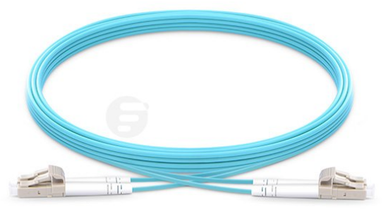
It is well known that traditional multimode patch cables are used to be applied in 100 Megabit Ethernet and 1 Gigabit Ethernet applications. Is it also able to support 10 Gigabit Ethernet? With the birth of OM3 patch cable, the answer is yes. (The word “OM” stands for optical multimode.) To fulfill the requirement of fiber optical market, the advanced multimode patch cable, OM3 patch cable is developed which can be also applied in 10 Gigabit Ethernet and transmit the signals at lengths up to 300 meters. As for the cost, it is just a little bit more expensive than original multimode patch cable that meets our need. The patch cables in the following figure are the OM3 patch cables, which are largely used in high-speed communication nowadays.
photo1.png
Superior OM4 Patch Cable
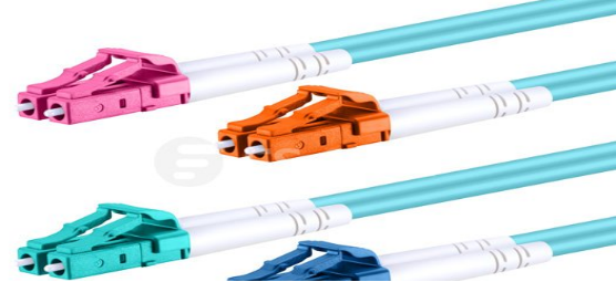
Apart from OM3 patch cable, there is a more superior multimode patch cable, OM4 patch cable which has come to fiber optic market. It is designed to support 10 Gigabit Ethernet at lengths up to 550 meters, which also supports 40 Gigabit Ethernet and 100 Gigabit Ethernet at lengths up to 150 meters. With the development of OM4 patch cable, the 40 Gigabit Ethernet and 100 Gigabit Ethernet could be available easily with a cost-effective method, thereby big preference is provided for the users. The patch cable in following figure is a kind of the OM4 patch cable for your reference.
photo2
Differences Between OM1, OM2 , OM3 and OM4
Compared with the OM1 and OM2 patch cables, OM3 and OM4 patch cables have been improved in many aspects. As for the diameter, both of their cladding diameters are 125 µm, but their core diameters are different. In details, the core diameters of OM1 patch cable is 62.5 µm, while the core diameters of OM2, OM3 and OM4 patch cables are smaller, 50 µm. As for the jacket colors, OM1 and OM2 patch cables are orange, but OM3 and OM4 are aqua. As for the optical source, traditional LED is used in OM1 and OM2 patch cables, as VCSEL is used in OM3 and OM4 patch cables with a lower loss. Besides, the bandwidth of the patch cables is designed to be wider and wider to face the high-speed network. From the following figure, we can know exactly the details of four multimode patch cables.
photo3
Each multimode patch cable is suitable for different applications. Generally, OM1 patch cable is always used to support 100 Megabit Ethernet applications at lengths up to 2000 meters; while OM2 patch cable is more commonly applied in 1 Gigabit Ethernet within a 550-meters transmission distance. As for OM3 patch cable, it is designed to support the applications of 10 Gigabit Ethernet, and its transmission distance can be 300 meters. As for OM4 patch cable, it is more superior that can support 40 Gigabit Ethernet and 100 Gigabit Ethernet and transmit signals at lengths up to 150 meters.
Conclusion
The development of science and technology will never stop, so does the improvement of multimode patch cable. With the unremittingly increasing requirement of today’s optical network, the multimode fiber optic cables would be developed to support 100 Gigabit Ethernet with longer transmission distance, even support 120 Gigabit Ethernet.

Thursday, October 20, 2016

Comparison of Multimode Patch Cable and Single-mode Patch Cable

Fiber optic patch cables are also referred to as fiber optic patch cords or fiber optic jumper cables, which are designed to connect the optical transmitter, receiver and terminal box in a simple way. With the greater advantages, the fiber optic patch cables become an inevitable choice to set up large-scale network, instead of copper cables. To meet the requirement of fiber optics market, the types of fiber optic patch cables are being more and more diversifying, which can be classified by fiber cable mode, fiber cable structure, connector types, etc.
When selecting the fiber optic patch cables, you’ll find many types of fiber optic patch cables in your list and you may feel a little confused about the selection. In this article, it will mainly introduce the differences between single-mode patch cable and multimode patch cable, which will help you have a good knowledge of this classification.
Structure Difference
In general, the fiber optic patch cable is composed of fiber optic cable and connectors in the view of the external structure. As for the internal structure, it has one transparent glass core with the property of high refractive index in the center of fiber optic patch cable, which makes optical signal transmitted as long as possible with low loss. Meanwhile, the core is covered by a protective cladding with the property of low refractive index, which strengthens the function of low signal loss. Besides, the fiber optic patch cable has a thick jacket outside to protect its core and cladding from the damage of external environment.
However, in addition to the similarities, there is a true structural difference between single-mode patch cable and multimode patch cable. Detailedly, the core diameter of the multimode patch cable is always 50 μm or 62.5 μm, while the core diameter of the single-mode patch cable is much smaller, 9μm. From the following picture, we can know exactly what the core diameter difference is between single-mode patch cable and multimode patch cable.
photo1
Color Difference
Fiber optic patch cables are always differently colored, such as, yellow, orange. Is there any classification according to distinct color? In principle, the color of the single-mode patch cable is yellow, as the multimode patch cable is orange, aqua or light blue. That’s to say, yellow optic patch cable would be a single-mode patch cable, and the aqua fiber patch cable is usually a multimode patch cable. The following figure provides the color difference between single-mode patch cable and multimode patch cable for your reference.
photo2
Application Difference
For its small core diameter, the single-mode patch cable can only carry the single optical signal in the same mode with different frequencies, which has little modal dispersion in the signal transmission. Meanwhile, its light source is provided by laser, which means that the signal power in single-mode patch cable is very strong. Therefore, the single-mode patch cable is commonly used in the applications for long distance transmission. What should be noted is that, due to its advantages of wide transmission band, big capacity and high speed, it is much more expensive than the multimode patch cable.
As for the multimode patch cable, it is clearly different from the single-mode one. It can carry more than one light signals in the different modes, which requires a much longer core diameter. Under this condition, it seriously causes the disadvantage of large dispersion. The longer the distance the signal is transmitted through multimode patch cable, the larger the dispersion is. Besides, its light source is provided by LEDs and the signal power in multimode patch cable is not so strong as in single-mode patch cable accordingly. Hence, the multimode patch cable is designed for short distance transmission with lower cost.
photo3
Conclusion
It can be concluded from this article that different fiber patch cables are designed for specific aims. If you want the high-speed and long-distance transmission, you are suggested to choose the single-mode patch cable; if low cost and short-distance transmission is demanded, the multimode patch cable must meet your needs. Just choose the suitable one for your network.

Friday, October 14, 2016

Things You Should Know About WDM System

What Is WDM?
WDM is a new technology widely used in optical network nowadays, with which you may be not very familiar. The word of WDM is the acronym of wavelength-division multiplexing. As its name implies, it is the technology of using different wavelengths of light to multiplex two or more optical carrier signals onto a single optical fiber, to some extent, strongly multiplies the capacity of the network. In its working process, without using additional fibers, optical carrier signals with different wavelengths are combined, transmitted together, and separated again through the single optical fiber. Meanwhile, each signal with different wavelength in the process does not interfere with each other as shown in the following figure. It takes great advantage of the enormous bandwidth of the optical fiber and makes bidirectional communications via one strand of fiber possible.
photo1
Why Is WDM Used?
With the rapid growth of the optical network, the communication exponentially increases, which has used many spare fiber cables installed with the optical network design. However, the spare fiber cables can’t meet the increased communication need and new capacity for the network is still required. How to solve this? At present, there are three methods to expand the capacity of our network: installing more fiber cables; increasing system bitrate to multiplex more signals and wavelength division multiplexing.
As for installing more fiber cables, it is popularly and largely used nowadays, for the cables are inexpensive and the installation is effective under currently advanced technology. But when conduit space is not available or major construction is necessary, the fiber optic cabling would be very complicated with high cost.
As for increasing system bitrate, considering that most of our systems have already worked in 2.5 GB/s network and need to upgrade to 10 GB/s network, which should change out all the electronics in our network. Hence, it is turned out to be an expensive way to multiplex more signals.
Compared with the previous methods, as WDM technology is developed fast and tended to be mature, using this method to expand the capacity of your network is a quite advisable, cost-effective way without adding cables or upgrading network. In simple terms: WDM creates virtual fibers, which is the best and simplest way to multiply fiber capacity in optic network.
How Does WDM Work?
As we all know about the working principle of a prism, when a white light beam moves from the air to the glass, a phenomenon of light dispersion occurs. The refractive index of glass varies with the different wavelengths of light, which makes the light with different wavelengths refracted differently and leave the prism at different angles, creating an effect similar to a rainbow. What should be noted is the process of light beam’s moving from the glass to the air, which is completely reverse. That’s to say, kinds of different color light pass through the prism that will be changed into a white light beam.
The working principle of WDM technology is the same as the prism. When multiple optical signals of differing wavelengths pass through the ingress, they will be combined into a single optical signal and transmitted together through a single optical fiber. In the transmission process, each signal with different wavelength does not interfere with each other. Once the single optical signal arrives at the egress, it will be separated into multiple optical signals of differing wavelengths again. To help you better understand the working principle of WDM technology, the following figure shows how does WDM use the different wavelengths of light to multiplex signals onto one single optical fiber.
photo2.png
Development of WDM System
The first WDM system uses a multiplexer at the transmitter to join the two signals together, a single fiber cable for signal transmission and a demultiplexer at the receiver to split the signals apart, which already enables the capacity of the network to be expanded without more fibers. At that time, the WDM system provides two channels over the single fiber cable for two normal wavelengths 1310 nm and 1550 nm. This system is also called normal WDM system or BWDM system sometimes.
The normal WDM system is too expensive to be largely deployed, which also has a very complicated working process. In order to optimize its function and reduce its fabrication cost, there are two superior WDM systems that are being developed sequentially for different applications, coarse wavelength-division multiplexing (CWDM) systems and dense wavelength-division multiplexing (DWDM) systems.
CWDM and DWDM are divided according to different wavelength patterns. In general, CWDM is designed to increase channels on one fiber cable for more wavelengths which varies from 1470 nm to 1610 nm, while DWDM supports the denser channels for wavelengths varying from 1547.72 nm to 1553.33 nm. The words “coarse” and “dense” reveal the difference in channel spacing. That is, the channel spacing for CWDM is 20 nm, as it for DWDM is denser, 0.8 nm. For the details of the basic difference between CWDM and DWDM, you can learn it from the following figure.
photo4.png
Comparison between CWDM and DWDM
CWDM and DWDM work with the same principle of multiplexing different wavelengths of light via a single fiber, but differ in wavelength patterns. The spacing of the wavelengths, the number of channels, and the ability to amplify the multiplexed signals are different, which are designed to be used for different application.
As for CWDM, it has a wider channel spacing which allows less sophisticated transceiver designs to be used with lower cost. As a result, CWDM is always the first choice for most applications. However, the signals transmitted in CWDM system cannot be amplified that caused a shorter transmission distance, approximately 100km. Taking this into consideration, CWDM is the cost-efficient way for short-distance optical networks.
In contrast to CWDM, there is no doubt that DWDM has a higher performance for its advantage of transmitting a greater number of signals with more stable wavelengths, due to its closer spacing of the wavelengths. Meanwhile, DWDM can also expand greater maximum capacity and transmit the signals longer, thus it is more suitable for long-distance optical networks. Accordingly, DWDM becomes more expensive.
Conclusion
The WDM revolution has already occurred with unanticipated swiftness, which plays an important role in meeting the increasing requirement of modern network. Although WDM technology is lack of a long history, with its great advantages, it is largely used in a really fast manner, dramatically promoting the network for high-volume data transmission over a single fiber cable.

Wednesday, October 12, 2016

40GBASE-SR BiDi QSFP Transceiver Module Solution

Challenges with Existing 40G Transceivers for Short Transmission
As we know, duplex LC interface is commonly used for most 40G transmission in long distances, for instance, 40GBASE-LR4 QSFP+ optics and 40GBASE-PLR4 QSFP+ optics, which works with high-performance in 40G long distance transmission. However, for 40G short distance transmission, 40GBASE-SR4 and 40GBASE-CSR4 are often used with high cost, which is clearly different from the traditional 10G transceiver. Generally, this kind of transceiver consists of a 12-fiber MTP/MPO connector and 12 fibers to accomplish the short distance transmission, with additional products like MTP/MPO cassettes for better cabling. Therefore, during the upgrading of short transmission from 10G to 40G, the cabling infrastructure becomes the biggest challenge that should be optimized. In order to solve this, researchers attempt to transmit 40G over duplex multimode fiber optic cables, instead of changing the complicated cabling infrastructure.
Is it possible to transmission 40G over duplex multimode fiber optic cables? With the birth of 40GBASE-SR BiDi QSFP transceivers, the answer is yes. For its advantage of transmitting 40G signals through only one duplex multimode patch cord for short transmission, this kind of 40G transceiver would be deployed in a cost-effective manner in fiber optic market.
Comparison Between 40GBASE-SR BiDi QSFP and Traditional 40G QSFP+ Transceiver
As for the traditional 40G QSFP+ transceiver like 40GBASE-SR4 and 40GBASE-CSR4, it usually has a 12-fiber MPO connector and 12 fibers. This kind of transceiver works with 4*10G transmission mode, occupying 4 fibers for sending signals, 4 fibers for receiving signals and 4 fibers wasted as shown in the following figure.
photo1
Compared with the traditional 40G QSFP+ transceivers, 40GBASE-SR BiDi QSFP optics use a much more straightforward transmission mode. With only a duplex LC patch cord to finish 40G transmission over MMF, it can perfectly achieve the migration from 10G to 40G. 40GBASE-SR BiDi QSFP takes full advantages of fiber optic multiplexing.
Working Principle of 40GBASE-SR BiDi QSFP Transceiver
Instead of changing the complicated cabling infrastructure, 40GBASE-SR BiDi QSFP transceiver is developed to transmit 40G signals over duplex multimode fiber optic cable. In general, there are mainly three steps for 4*10G signals transmitting via 40GBASE-SR BiDi QSFP module.
The first step is to combine signals electrically. In the electrical combination, the four 10G signals are combined together into two 20G signals. And the second step is an optical combination, using two different wavelengths to transmit the two 20G signals through the same fiber strand. Finally, the two 20G signals are sent to the other 40GBASE-SR BiDi QSFP module on the target device via the single optical fiber. The 40G signals are eventually received by the other 40GBASE-SR BiDi QSFP module on the other end of the optical fiber. What should be noted is that the process for receiving signals is reverse. This is how do a pair of BiDi QSFP transceivers send and receive 40G signals over a duplex fiber optic patch cable. To help you better understand this module, the following figure shows the basic working principle of the 40GBASE-SR BiDi QSFP transceiver.
photo2
Besides, in the second step of 40G signals transmission, 850 nm and 900 nm wavelengths are most commonly used that support reliable transmission over multimode fiber optic cables at lengths up to 150 meters over OM4 and 100 meters over OM3. The two different wavelengths can respectively transmit 20G signals via the same fiber strand, which perfectly fit the 40G short distance transmission in data center. You can learn the internal structure of the 40G BiDi QSFP module and how do a pair of BiDi QSFP modules work with each other in the following figure.
photo3
High Density Cabling Solution for 40GBASE-SR BiDi QSFP Modules
With the development of 40GBASE-SR BiDi QSFP module, the 40G network for short distance transmission could be built easier and faster with a cost-effective method, instead of changing the complicated cabling infrastructure, thereby big convenience is provided for the users. Generally, a pair of duplex LC-LC multimode fiber optic patch cable is suggested to scale your 40G network, with OM3 and OM4 highly recommended. If high density cabling in data center is required, you can choose a new version of LC patch cord—LC-HD duplex multimode fiber optic cable with a tab attached on the connector to reach easier.

Tuesday, October 11, 2016

How Much Do You Know About Fiber Optic Attenuator?

The fiber optic attenuator is also referred to as optical attenuator, which is generally used in single-mode long-haul application. Meanwhile, it is also known as transmission loss attenuation. From its name, it is easy to know that the function of optical attenuator is optical signal attenuation. That’s to say, the fiber optic attenuator is designed to decrease the level of signal power when the optical signal is propagated along a free space or a fiber optic cable.
Why Is the Fiber Optic Attenuator Used?
When we talk about optical power in light transmission, we always think the stronger the power is, the better the transmission performance will be. Then, why the fiber optic attenuator is developed? Why we should attenuate the optical power? Will the fiber optic attenuator have a negative effect on optical signal transmission?
As we know, in the single-mode fiber optic cable, the light source is laser which is really strong, so that the light signal can be transmitted as long as possible. However, if the transmission distance is not so long, too much optical power will overload the fiber optic receiver. Furthermore, if there is a mismatch between the transmitter/receiver that the optical power sent from the transmitter is too strong, the receiver must meet the optical overload. In this case, the fiber optic attenuator is developed and should be inserted in the receiver side to reduce the optical power into a bearable load, then optical overload can be avoided.
In general, the fiber optic attenuator is a passive optical device which can decrease the level of signal power according to its design. It is commonly used for adjusting or testing the power of the light signal in optical communication to ensure the good working condition of the optical system.
Working Principles of Fiber Optic Attenuator
With the rapid development of optical technology, the optical signal attenuation can be dealt with by many methods, for instance, gap-loss, reflection, absorption, diffusion, scattering, deflection, diffraction, and dispersion, etc.
The most popular method used by the fiber optic attenuator is the absorptive principle, which is very simple by setting a material like sunglass to absorb the extra light power and convert it to heat. The fiber optic attenuator running with absorptive principle has a working wavelength range, in which it can absorb all light power equally. What’s the most important is its superiority that it will not reflect or scatter the light into an air gap, which may not cause the unwanted back reflection in the fiber communication system.
photo1
As for the fiber optic attenuator working with reflective principle, the major power loss in optical fiber is caused by the reflection. One of its advantage is to reflect a known quantity of the light signal, thus only allowing the desired portion of the signal to be propagated in the fiber communication system.
In short, there are many types of fiber optic attenuators operating with various principles, which are developed to use in different occasions. You can just choose the one suitable for the optic system you use.
Types of Fiber Optic Attenuators
Similarly, two kinds of fiber optic attenuators which are developed by different forms, are typically classified as fixed or variable attenuators. Both of them have unique characteristics to meet the requirements in different occasions. Here are the detailed characteristics of fixed and variable attenuators for your reference.
Fixed Fiber Optic Attenuator and Its Application
The fixed fiber optic attenuator, as its name implies, is designed to reduce the signal power with a set, unchanged level, which is typically used for single-mode applications. Theoretically, it can be fabricated to provide any amount of attenuation. In the signal transmission process, when the signal approaches a device or node in a fiber communication link, the power will be reduced to a level that is suitable for its application. It is designed to make signal reflection as small as possible, therefore more accurate transmissions of data can be sent.
photo2
Generally, the fixed fiber optic attenuator can be classified by the connector type and the attenuation level. The attenuation values of fixed fiber optic attenuators are typically between 1 and 30 dB. Meanwhile, fixed fiber optic attenuators are available in LC, SC, ST, FC connector. For instance, SC 3dB fixed fiber optic attenuator, can provide 3dB optical attenuation with the SC fiber optic connector.
Variable Fiber Optic Attenuator and Its Application
Clearly different from the fixed fiber optic attenuator, the variable fiber optic attenuator offers a range of attenuation values with flexible adjustment, which is usually used for testing and measuring, or equalizing the optical power between different signals. In the signal transmission process, the power attenuation is done by directly blocking the beam.
photo3
At present, there are two types of variable fiber optic attenuators, the stepwise variable attenuator and the continuous variable attenuator. The stepwise variable attenuator is able to change the attenuation of the signal in known steps such as 0.1 dB, 0.5 dB, or 1 dB, which may be used for dealing with multiple optical power sources. As for the continuous variable attenuator, it is designed to quickly and precisely change the optical attenuation on demand, commonly used in uncontrolled environments where the input and/or output device needs to change continually.
Conclusion
The fiber optic attenuator is an important passive optical device, which can reduce the level of signal power according to the user’s requirement as expected. As present, it is largely used in optical communication with the aim of preventing the receiver from optical overload, thereby big convenience is provided for the users.

Friday, October 7, 2016

Introduction of Multimode Fiber Optic Cable

The multimode fiber optic cable is commonly applied in short distance communication. It has the properties of low insertion loss, good repeatability, high return loss and excellent temperature stability, which is largely used nowadays. However, it has a serious disadvantage of large dispersion. The longer the distance the signal transmits, the larger the dispersion is. Therefore, the multimode fiber optic cable is suggested to be used in the applications for short distance transmission.
Comparison With Single-mode Fiber Optic Cable
Clearly different from the single-mode fiber optic cable, the multimode fiber optic cable can carry more than one light signal in the different modes, which requires a much longer diameter of its core. In general, the core diameter of multimode fiber optic cable is about 50-100 µm. However, because of its large dispersion, the multimode fiber optic cable is only suitable for short communication.
photo1
Figure 1. Structure of single-mode fiber optic cable and multimode fiber optic cable
Furthermore, the multimode fiber optic cable is only suitable in 1 Gigabit Ethernet., while the single-mode fiber optic cable is able to transmit signals in 10 Gigabit Ethernet. But considering the manufacturing cost of single-mode fiber optic cable, it can’t be largely used in 10 Gigabit Ethernet. Therefore, improving the performance of multimode fiber optic cable to support 10 Gigabit Ethernet has become an inexorable trend.
Development of Multimode Fiber Optic Cable
With the improvement of network applications, 10 Gigabit Ethernet seems to have been inevitable. To meet the requirement of fiber optic market, the advanced multimode fiber optic cables are developed which can be also applied in 10 Gigabit Ethernet. As for the cost, the advanced multimode fiber optic cable is a little bit more expensive than original multimode fiber optic cable.
At present, there are four types of multimode fiber optic cables in fiber optic market, OM1, OM2, OM3 and OM4. The word “OM” is the acronym of optical multimode.
As for the four types of multimode fiber optic cables, they have different properties and can be used in different applications. In general, OM1 is always used to support 100 Megabit Ethernet applications; while OM2 is more commonly applied in 1 Gigabit Ethernet. As for OM3, it is designed to support the applications of 10 Gigabit Ethernet. And OM4 is more superior which can support 100 Gigabit Ethernet.
Basic Differences Between OM1, OM2, OM3 and OM4
The multimode fibers can be distinguished by their core and cladding diameters. All cladding diameters of the four multimode fibers are 125 µm. But their core diameters are different. The core diameter of OM1 is 62.5 µm, while the core diameters of OM2, OM3 and OM4 are 50 µm.
OM1 and OM2 have the orange jackets and their optical source is LED. Different from OM1 and OM2, OM3 and OM4 have aqua jackets and their optical source is 850nm VCSEL.
They can also be described by different bandwidth. OM1 has 200 MHz*km bandwidth, and OM2 has 500 MHz*km bandwidth. As for OM3, it provides sufficient bandwidth to support 10 Gigabit Ethernet, which is 2000MHz*km. To be used in 100 Gigabit Ethernet, the design of OM4 maximizes the bandwidth, so that OM4 has 4700MHz*km bandwidth, much wider than previous types.
photo3
Figure 2. Basic differences between OM1,OM2,OM3 and OM4
OM1, OM2, OM3 and OM4 in Different Applications
All of the four types of multimode fiber optic cables can support 100 Megabit Ethernet for communication at lengths up to 2000 meters.
In 1 Gigabit Ethernet, the transmission distances of OM1 can be 275 meters; the transmission distances of OM2 and OM3 are 550 meters at most; and the transmission distances of OM4 is the longest, 1000 meters.
In 10 Gigabit Ethernet, OM1 can only transmit signals at lengths up to 33 meters; OM2 has the performance of 82 meters transmission distance; OM3 can transmit longer, 300 meters; and OM4 can transmit longest, 550 meters.
In order to support 40 Gigabit Ethernet and 100 Gigabit Ethernet, OM3 and OM4 have been developed. It should be noted that OM3 can be used in both 40 Gigabit Ethernet and 100 Gigabit Ethernet with 100 meters transmission distance. As for OM4, it is a further improvement that can support both 40 Gigabit Ethernet and 100 Gigabit Ethernet at lengths up to 150 meters.
photo2
Figure 3. OM1,OM2,OM3 and OM4 in different applications
In short, OM1 is always used for 100 Megabit Ethernet applications which can transmit 2000 meters with the lowest cost; while OM2 is more commonly used in 1 Gigabit Ethernet. These two multimode fiber optic cables are not very suitable for high-speed communication nowadays. Therefore, to fulfill the need of the fast network development, advanced multimode fiber optic cables OM3 and OM4 are invented. OM3 is designed to support the applications of 10 Gigabit Ethernet, and OM4 is more superior that can support 100 Gigabit Ethernet at lengths up to 150 meters.
Conclusion
With the fast development of network, the multimode fiber optic cables would be improved to support 40 Gigabit Ethernet and 100 Gigabit Ethernet with longer transmission distance, which is the future development prospect in fiber optics market.

Thursday, October 6, 2016

The Development of Fiber Optic Transceiver

Introduction of Fiber Optic Transceiver
The fiber optic transceiver is consisted of a transmitter on one end and a receiver on the other end which are designed to work separately. In another words, the transmitter and the receiver can work together without each others’ impact. Detailedly, for data transmission, the transmitter will convert the electrical signal into light signal and transmit the light signal to the receiver. Once the receiver receives the light signal, it will convert the light signal into electrical signal again. Finally, the information will be transmitted to the computer to understand. What should be noted is that the receiver and the transmitter can work with their own circuitry and transmit the data in both directions.
To fulfill the need of fiber optic transceiver market, the type of fiber optic transceivers diversifies to achieve higher and higher transmission speed and smaller and smaller size, such as: GBIC, SFP, XFP, SFP+, etc.
photo1
Figure 1. The development of fiber optic transceiver
The Emergence of 1*9 Fiber Optic Transceiver
1*9 fiber optic transceiver is the earliest fiber optic transceiver, which is stationary and weld directly in circuit board of a communication equipment. As time goes on, it develops gradually towards miniaturization and hotplug support.
The emergence of 1*9 fiber optic transceiver is of epoch-making significance in the history.
photo2
Figure 2. 1*9 Fiber Optic Transceiver
The GBIC Transceiver and Its Application
The GBIC transceiver is also referred as gigabit interface converter transceiver, which was published in 1995. The design of GBIC transceiver is to handle the optical-electric conversion. In another words, the transmitter of GBIC transceiver can convert the electric currents into the light signal and send it to its receiver. Then the receiver will get the light signal and convert it into the electric currents.
To meet the requirement of high-speed network, the GBIC transceiver is designed to transmit at 1 Gbps or more in fiber optic and Ethernet systems. Meanwhile, the design of hot swappable electrical interface makes GBIC transceiver easy to install, so that it can be engaged and disengaged without turning off the system. Besides, one GBIC transceiver can support a wide range of media for hundreds of kilometers, which is very important for the development of fiber optic transceiver.
photo3
Figure 3. GBIC Transceiver
The SFP Fiber Optic Transceiver and Its Application
With the fast development of the network, the disadvantages of GBIC transceiver have gradually appeared, because of its big size. To keep pace with the trend of network development, the SFP fiber optic transceiver was invented in 2001.
The SFP fiber optic transceiver is one of the variation of the GBIC transceiver, which can also be called small form-factor pluggable transceiver or mini-GBIC. Its function is the same as GBIC transceiver, but it has a smaller form factor than GBIC transceiver. Also, the data rate has been improved, which is 1-2.5 Gbps.
The SFP fiber optic transceiver is a kind of hot-pluggable transceiver which is commonly applied in the field of telecommunication and data communication. Due to its smaller size and higher speed, it is largely used, instead of GBIC transceiver.
photo4.png
Figure 4. SFP Transceiver
The XFP and SFP+ Fiber Optic Transceiver
The development of fiber optic transceiver market is extremely rapid. On the basis of miniaturization and hotplug support, the products are being developed with higher and higher speed and performance. For instance, X2 fiber optic transceiver, XENPAK fiber optic transceiver , XFP fiber optic transceiver and SFP+ fiber optic transceiver.
The XFP fiber optic transceiver was published in 2002 and SFP+ fiber optic transceiver was published in 2006. And both of the data rate can be 10 Gbps. The main difference between XFP and SFP+ transceiver is the different size. The SFP+ transceiver is smaller than XFP transceiver, which has the same size as SFP transceiver.
With the advantage of small size, hotplug support, low cost and high performance, the SFP+ transceiver meets the standard of high requirement and density and becomes the leading products in 10 Gbps market, which makes XFP transceiver obsolete.
photo5
Figure 5. XFP Transceiver
photo6
Figure 6. SFP+ Transceiver
The New Transceivers for 40/100G Network
As time goes on, SFP+ transceiver is not able to meet the requirement of high data rate. With the need of wider and wider bandwidth, the transceiver for 40/100G network has been developed and put into use.
As for the 40G QSFP+ SR4 and QSFP+ LR4 transceiver, their connectors are MPO/LC connectors. 40G QSFP+ SR4 transceiver is designed for short transmission, while QSFP+ LR4 transceiver is to use in long distance transmission.
photo7
Figure 7. QSFP+ Transceiver
As for the 100G CFP/CFP2/CFP4 transceiver, their connectors are LC connectors, too. All their data rate can achieve 100 Gbps. However, they have a apparent difference, the different size. CFP transceiver has already meet 100 Gbps high data rate, but its big size can’t fulfill the requirement of high-density data center. Take it into consideration, CFP2 and CFP4 transceiver have been developed successively.
photo8
Figure 8. CFP/CFP2/CFP4 Transceiver
Conclusion
With the fast development in fiber optic communication, people always go after better transceiver with higher data rate, lower cost, smaller size and higher performance. Therefore, more and more advanced transceivers will be developed successively to achieve a thriving and prosperous prospect like a hundred flowers in bloom.

Introduction of Commonly Used Fiber Optic Patch Cables

Introduction of Fiber Optic Patch Cable
The fiber optic patch cable is a jumper wire invented to connect the optical transceiver, receiver and terminal box, which facilitates the data transmission with a simple and low-loss way. Compared to the traditional copper cable, fiber optic cable has a great improvement in the property of repeatability, confidentiality, transmission speed and transmission capacity to realize the data transmission with low loss.

Therefore, fiber optic patch cable is an inevitable choice to set up large-scale and long-distance network, instead of copper cable. 
Structure of Fiber Optic Patch Cable
In general, the fiber optic patch cable is composed of fiber optic cable and connectors in the view of its external structure.

Figure.1 The external fiber optic patch cable.
As for its internal structure, there is a transparent glass core with the property of high refractive index in the center of fiber optic patch cable, which makes light signal transmitted as long as possible with low loss. The diameter of the core in an ordinary fiber optic patch cable is about 125µm, as wide as a single hair of human. With the development of fiber optic patch cable, the diameter of the core is smaller and smaller. For instance, the diameter of the core in the single-mode cable is only 9 µm, much smaller than ordinary cable’s. Furthermore, the core is covered by a protective cladding with the property of low refractive index, which strengthens the function of low signal loss. Besides, the fiber optic patch cable has a thick jacket outside to protect its core and cladding from the damage of external environment.
Figure.2 The internal structure of fiber optic patch cable.

Commonly Used Fiber Optic Patch Cables
When selecting the fiber optic patch cables to use, you’ll find many types of fiber optic patch cables in your list and you may feel a little confused about the selection. Here are the detailed characteristics of some commonly used fiber optic patch cables for your reference which may meet your need.

Fiber Optic Patch Cables Classified by Transmission Medium
On the basis of the different transmission medium, the fiber optic patch cables can be divided into two types, single-mode fiber cable and multimode fiber cable.

The Characteristics of Single-mode Fiber Cable and its Application

The single-mode fiber cable can only carry a single light signal in the same mode with different frequencies, which has little modal dispersion in the signal transmission. As a result, it is designed for long distance transmission. For its advantages of wide transmission band, big capacity, high speed and long transmission distance, is it also more expensive than the multimode fiber cable.

The Characteristics of Multimode Fiber Cable and its Application
Clearly different from the single-mode fiber cable, the multimode fiber cable can carry more than one light signals in the different modes, which required a much longer diameter of its core. However, it causes a serious disadvantage of large dispersion. The longer the distance the signal is transmitted through multimode fiber fiber cable, the larger the dispersion is. Therefore, the multimode fiber cable is commonly used in the applications for short distance transmission.


Figure.3 The different signal transmissions between single-mode fiber cable and multimode fiber cable.

Fiber Optic Patch Cables Classified by Cable Quantities
According to the different cable quantities, there are two types of fiber patch cables commonly used nowadays, simplex fiber patch cable and duplex fiber patch cable.

The Characteristics of Simplex Fiber Patch Cable and its Application
The simplex fiber patch cable has only one fiber optic core and cladding. For the only one fiber, the signal transmission through simplex fiber patch cable can be running in one direction at a time. However, as time goes on, the new simplex fiber patch cable is developed which designed for transmitting the duplex signals respectively by using two light signals with different wavelengths. As a result, the data can be transmit in two directions at the same time. Compared to the duplex fiber patch cable, the simplex fiber patch cable has a great improvement in the high speed of sending and receiving the signals, which also saves the optical fiber resource.
Figure.4 The simplex fiber patch cable.

The Characteristics of Duplex Fiber Patch Cable and its Application
The duplex fiber patch cable is also tight-buffered and jacketed like the simplex fiber patch cable. But there are two separate simplex cables with their own jackets linked together by a kind of material. It works simply, carrying the signals by two separate simplex cables. When the one cable is sending the signal in one direction, another cable can receive the signal and send another signal in the other direction simultaneously. The reliability of transmitting signals by duplex fiber patch cables is higher than transmitting by simplex cables, but the speed of transmitting signals by duplex fiber patch cables is slower. For the sake of high reliability of sending and receiving signals, the duplex fiber patch cable must be a good choice.

Figure.5 The duplex fiber patch cable.

Conclusion
To meet the requirement of fiber optic cable market, the types of fiber optic cable is being more and more diversifying. It can be concluded from this article that the different fiber cables are designed for specific aims. In short, the single-mode fiber cable is suitable for long distance transmission, while the multimode fiber cable is commonly used in the applications for short distance transmission. If you want the high-speed transmission, you are suggested to choose the simplex fiber patch cable; if the reliability of transmitting signals is required, the duplex fiber patch cable must meet the need.