Thursday, December 29, 2016

Keystone Jack Overview

What Is the Keystone Jack?
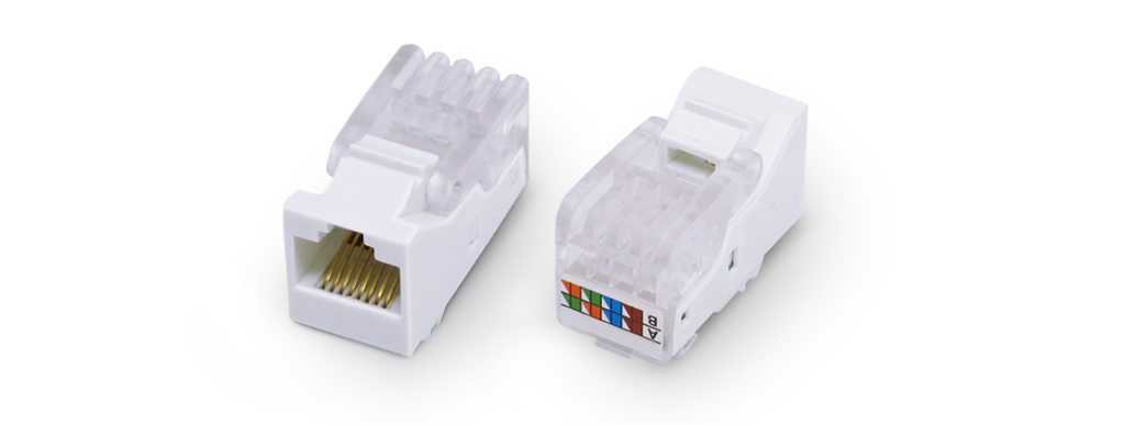
The keystone jack is a kind of female connector always attached to the end of network patch cable, which is designed for data communications, especially local area networks (LANs). This kind of connector is generally fabricated in a standardized size, hence it can be versatile to work with all brands of patch panels, surface mount boxes and keystone wall plates. As for the structure of keystone jack, you can learn it from the following figure.
Keystone Jack

Why the Keystone Jack Is Used?
The keystone jack is basically universal in all the brands of patch panels, keystone wall plates, etc. Just taking its installation in the keystone wall plate as an example, various types of keystone jacks can be easily and fast mounted into one wall plate with many ports. Meanwhile, it offers multiple configuration options in data centers and networks utilizing patch panels, as well. The advantage of versatility is one of the most important factor that makes the keystone jack so popular in data communications.
Another important factor is its advantage of diversity. At present, there are many kinds of keystone jacks available in the market, such as, cat5e keystone jack, cat6 keystone jack, cat6a keystone jack, etc. Even special variations of the keystone jack has come into market in recent years to meet the growing requirements of the network. Among these types, the high-density keystone jack has focused on much of the attention that has the ability to maximize the working space where you may feel constrained. As for its application, the high-density keystone jack always works with high-density patch panel, allowing you to fit more individual jacks into a single patch panel. Since the keystone jack has been so diversified, it is an ideal solution for home theater installations or other applications where multiple connections are required.
Furthermore, using the keystone jack can support a clean and professional look for the end connection of the network patch cable, thereby a neat and secure connection can be provided to the home network. Besides, the extra space of the wall plate can greatly save room without leaving an unsightly empty hole, allowing for a safe and secure future expansion at the same time.
How to Punch Down a Keystone Jack?
Correct punching down a keystone jack can greatly ensure the performance and stability of the connection. To help you correctly punch down the keystone jack, here will provide the detailed instructions for punching down a cat5e keystone jack as an example.
  • Prepare the required tools for punching down a cat5e keystone jack, including a cable stripper tool, a cable cutter, a cat5e patch cable, a cat5e keystone jack.
  • Use the stripper tool to strip the jacket (approximately one inch) in the tip of the cat5e patch cable. You should adjust the stripper in a proper position to score the jacket, avoiding scratching the twisted cables underneath.
  • Check and confirm that the four pairs of wires with different colors inside the jacket are in good condition to ensure a successful connection.
  • Untwist and straighten all the four pairs of wires and separate them into eight exposed, individual wires.
  • Remove the plastic cap from the back of the cat5e keystone jack, and confirm the color order marked beside each termination post of the cat5e keystone jack.
  • Put the punch down tool on the outside of the cutting blade, use it to push down each wire of the cat5e patch cable, and lock the wires in their corresponding position by matching the wire color with the color order you find in the cat5e keystone jack.
  • After punching down all the eight wires, you should use the cable cutter to cut all the excess wires outside the keystone jack.
  • Reattach the plastic cap to the back of the cat5e keystone jack.
  • Test and confirm that all the wires have the proper connections.
Conclusion
In short, the keystone jack is very commonly used in data communications due to its versatility and diversity. Meanwhile, it is capable of offering a clean, secure and professional connection and a safe and secure future expansion. Since it has been so popularly used, you are suggested to acquire the skill of punching down the keystone jack that is very easy to grasp and can save a lot of money and time.

Tuesday, December 27, 2016

Guides for Selecting Ethernet Patch Cable

Ethernet patch cable, the copper-based patch cable, may perform not so good as fiber optic patch cable in deploying Ethernet network, but it is still very commonly used in many applications, such as PCs, routers, and switches, as an accessible, popular and low-cost solution. At present, there are various types of Ethernet patch cables available in the market that may not be very easy to classify if you are not familiar with them. In this paper, it will introduce four widely used types of Ethernet patch cables according to different standards that you can take as reference to select the most suitable one for deploying your network.
STP and UTP Cable
There are two types of Ethernet patch cables according to whether the cable is shielded or not, known as shielded twisted pair (STP) cable and unshielded twisted pair (UTP) cable. As for the structure of these two types of copper cables, here offers their differences in the following figure for your reference. Besides, it is worth mentioning that shielding is one of the common methods to decrease or avoid EMI, aiming at protecting the whole cabling system.
utp vs stp cable
As for the STP cable, it is always made up of even wires that are shielded by a metallic substance. Just taking an eight-strand cable as an example, all the four pairs of the wires are twisted, shielded and then wrapped in another metallic protector, as shown in the above figure. Through shielding, cancellation and wire twisting, the STP cable can be well protected from interference. It is highly recommended to use the STP cable in industrial settings with high amounts of electromagnetic interference (EMI), such as factories with large electronic equipment. However, there is an important issue that should be paid attention to if you choose the STP cable to deploy Ethernet network. After installation, you should check and ensure that it is installed and grounded properly, or the shielded Ethernet cable will act as an antenna and pick up signals when your network runs.
As for the UTP cable, it is easy to learn that it is designed without shielding. Compared to the STP cable, it is much simpler to install and less expensive due to its unshielded property. But without shielding, how to reduce or avoid interference when using the UTP cable? Or this kind of cable has no ability to decrease the interference? In fact, the UTP cable depends on the twisted pair inside the cable to cancel EMI. Meanwhile, it does not require as much maintenance but can transmit data as fast as the STP cable, since it don’t rely on the outer shielding. As for its application, it is always used in domestic and office Ethernet connections, and in any area where there is not a high degree of EMI.
Solid and Stranded Cable
The solid and stranded cable with different features are designed for various applications. Knowing their features and acquiring when and where they should be used will be helpful for you to improve networking performance and efficiency when designing your network. The following will introduce the structure and advantages of these two kinds of copper cables, then you can have a good knowledge of which should be selected and used for deploying your network.
solid vs stranded cable
As shown in the above figure, the solid cable consists of a single, solid conducting wire, insulated with non-conductive materials. With the feature of large-diameter wire, it is physically stronger than the stranded cable and capable of remaining stable over a wider range of frequencies, providing superior electrical characteristics and supporting long transmission with high data rates. Meanwhile, it has a lower DC resistance and a lower susceptibility to high frequency effects than the stranded cable due to its large-diameter wire. All these advantages make the solid cable better suited to the new and emerging high-speed Ethernet applications. However, the large diameter feature of solid cable brings a serious disadvantage at the same time. It could be easy to be break for lack of flexibility as they cannot be flexed or bent for many times without breaking. Hence, the solid cable is an ideal solution for horizontal cabling applications with long transmission distance.
Greatly different from the solid cable, the stranded cable is composed of a bundle of twisted, small gauge wire strands. Its diameter of each individual wire strand is much smaller than that of the solid cable, making it much more flexible and hard to break even if it is repeatedly flexed or bent. Although the stranded cable is not so reliable as solid cables for long distance transmission, it features high flexibility that makes itself easy to constantly plugged, unplugged, bent or installed without harm or risk of performance failure, as an optimal choice for short distance transmission.
Conclusion
From this paper, we can learn four widely used types of Ethernet patch cables with different features that are suitable for different applications. The STP cable is always applied in industrial settings with high amounts of EMI, while the UTP cable is more commonly used in domestic and office Ethernet connections, and in any area where there is not a high degree of EMI. If you want to establish a horizontal, long-distance network with high reliability, the solid cable is strongly recommended. But if long distance is unneeded, you are suggested to use the stranded cable which is a good choice for short distance transmission with high flexibility. In short, choosing the most suitable Ethernet patch cable to deploy your network that can greatly improve your network performance and extend life span of your equipment.

Friday, December 23, 2016

Properly Terminate Fiber Optic Cables for a Smooth Connection

In the optical network deployment, fiber optic termination should be an unavoidable and vitally important procedure that enables fiber cross connection and light wave signal distribution. Only when the fiber optic cables in the network are terminated properly can they be protected from dirt or damage so as to achieve a smooth and steady network. Meanwhile, proper fiber optic termination can efficiently avoid the excessive loss of light when the network runs, which strengthens the smooth connection. But how to properly terminate fiber optic cables to ensure a smooth connection? Let’s talk about this topic and find the most suitable method to terminate fiber optic cables for your network.
Proper Methods for Fiber Optic Termination
There are two methods for terminating fiber optic cables, using connectors and splicing, each of which allows for a smooth connection with low light loss and back reflection in a proper manner. We can learn these two methods in the following figure. The method of using connectors to terminate fiber optic cables is shown in the top right corner that is able to mate two fibers for a temporary joint, while the other method is splicing which has the ability to create a permanent joint between the two fibers. As for the step-by-step instructions of these two methods, it will be introduced detailedly in the following text.

Using Connectors to Terminate Fiber Optic Cables
You may often hear about the descriptions like LC to LC patch cord, LC to SC patch cord and LC to FC patch cord when choosing fiber patch cords to deploy your network. Do you understand what do the words “LC” “SC” and ”FC” mean? In fact, they stand for three kinds of connectors that are to terminate the ends of fiber optic cables, with the aim of connecting and disconnecting two fibers for many times without affecting the optical performance of the fiber circuit. To get a smooth fiber circuit, the following will illustrate how to use the connectors to properly terminate fiber optic cables.
  • Take out the fiber optic cable that you want to terminate and prepare a fiber cleaver for the termination.
  • Strip away the outer jacket, buffer and cladding of the fiber optic cable and cut away the excess aramid yarn.
  • Lightly score the fiber by pressing the fiber cleaver. Don’t use the cleaver more than once to score the fiber, so that the fiber will not be broken by unexpected, additional notch.
  • Along the score, bend the fiber and the tongue of the cleaver together to break the fiber.
  • Use the scale on the cleaver for measuring the bare fiber to ensure that it is long enough, so that it can reach the fiber inside the connector and make the termination work finally.
  • Utilize alcohol wipes with at least 90% isopropyl alcohol content and lint-free material to clean the fiber.
  • Carefully insert the bare fiber into the connector and crimp the connector onto the buffer.
Notices: Please check and confirm the right types of connectors and their polishing styles before making the termination to avoid non-corresponding installation. Moreover, test periodically during the installation, rather than testing them all after the job is completed to eliminate the possibility of repeating the same errors throughout the installation.
Splicing to Terminate Fiber Optic Cables
When the fiber cable is too long or there are various fiber cables that needs to be mixed, the splicing is strongly recommended to do the fiber optic termination. For instance, splicing a 48-fiber cable and six 8-fiber cables together. Meanwhile, if a buried finer cable is accidentally severed, you are also suggested to use the splicing method to restore the fiber optic cable. The following will introduce the procedures of fusion splicing which may be useful for you to make a proper fiber optic termination.
  • Prepare the two fiber ends that need to be spliced together.
  • Strip the protective coating, jackets, tubes, strength members, etc, and only leave the bare fiber showing.
  • Clean the fiber cables and use score-and-break method to score the fibers, for the sake of proper splicing.
  • Properly align the cleaved end-faces of the two fibers, and then utilize an electrical arc to melt them. Hence, the two fiber ends can be permanently welded together.
  • Finally use the heat shrink tubing, silicone gel and mechanical crimp protector to protect the splice from outside elements and breakage.
Conclusion
From the mentioned above information, we can easily acquire two proper methods for fiber optic termination, using connectors and splicing, both of which are the useful and effective solutions to achieve smooth connections. Using these two methods to terminate fiber optic cables can protect the fibers from being damaged, avoid the excessive loss of light and keep a stable performance for your network.

Wednesday, December 21, 2016

In-Depth Study of CWDM Transceivers

It is easy to learn that CWDM stands for Coarse Wavelength Division Multiplexing, which belongs to one of WDM technologies. With the fast development and gradual maturity of WDM technologies, CWDM technology becomes popularly used in recent years that allows for expanding network capacity without more fibers and supporting less expensive and power consuming system. For all these advantages, CWDM technology is applied in many optical equipment. One of the most popular equipment that uses this technology is CWDM optical transceiver, which will be introduced in the following text.
CWDM Transceiver
CWDM transceiver is a kind of optical module typically working with CWDM technology, which is designed for connecting the existing network equipment with CWDM multiplexers/demultiplexers (Mux/Demux). As for its working principle, it is able to combine optical signals with different wavelengths in the multiplexers side and transmit the integrated signal through a single fiber, while splitting the integrated signal into several signals with different wavelengths in the demultiplexers side. And there are eighteen channels available in CWDM transceiver for transmitting signals with different wavelengths from 1270 nm to 1610 nm, such as 1270 nm, 1290 nm, 1310 nm, 1330 nm, etc.
At present, CWDM transceiver can be simply divided into four types, CWDM SFP, CWDM SFP+, CWDM XFP and CWDM X2, both of which will be studied in details. Besides, to better know CWDM transceivers, here offers the figure for the appearance of the four CWDM transceivers for your reference.
cwdm transceiver
CWDM SFP
CWDM SFP is a kind of hot-pluggable optical module, which is SFP MSA (Multi Sourcing Agreement) and IEEE 802.3 & ROHS compliant. Compared to other CWDM transceivers, CWDM SFP is the most commonly used module that connects LC duplex single-mode patch cord to support 1G, 2G and 4G Ethernet network at lengths up to 200 km. In its working process, it enables the network capacity to be increased by transmitting multiple data through a single fiber, with the function of combining optical signals with different wavelength into an integrated signal.
As for the application, CWDM SFP can support the CWDM passive optical system combing CWDM OADM (optical add/drop multiplexer). If you use CWDM SFP to work with transponders and media converters, you will find that the two optical components convert the existing equipment with standard wavelengths or copper ports to CWDM wavelengths in a very convenient way.
CWDM SFP+
CWDM SFP+ is an upgraded version of CWDM SFP that offers a simple way to make 10G network connection. It has the ability to work with up to eight channels for transmitting 10G signals at the wavelengths including 1470 nm, 1490 nm, 1510 nm, 1530 nm, 1550 nm, 1570 nm, 1590nm, and 1610 nm, through single-mode fiber strands. And it can be used in parallel with other SFP+ devices on the same platform.
In contrast to CWDM SFP, it is much more expensive. However, taking 10G Ethernet applications into consideration, CWDM SFP+ is really a cost-effective solution in campus, data center and metropolitan area access networks. After all, it allows for increasing the bandwidth of an existing 10G Ethernet optical infrastructure without adding new fiber strands.
CWDM XFP
Just like CWDM SFP+, CWDM XFP is also used for 10G Ethernet applications with Z-direction design, which complies with CWDM XFP MSA. What’s about the cost? It is also nearly the same as that of CWDM SFP+. Meanwhile, it can transmit 10G signals at the distance up to 100 km, which depends on the wavelengths, fiber types and the CWDM Mux/DeMux insertion loss. Besides, it is mainly used in Storage, IP network and LAN applications, working with the wavelengths from 1270 nm to 1610 nm.
CWDM X2
In comparison with the previous three CWDM transceivers, CWDM X2 is the most expensive one which is suitable for CWDM optical data communications like 10G Ethernet and 10G Fibre Channel applications. Similar to CWDM XFP, it also works with the wavelengths from 1270 nm to 1610 nm, supporting 10G transmission at lengths up to 80 km over SC duplex single-mode fiber cable.
Conclusion
CWDM transceivers can greatly expand the network capacity without additional fibers by connecting the existing network equipment with CWDM multiplexers/demultiplexers (Mux/Demux). It is really a cost effective solution for higher capacity that allows for a highly flexible and available multi-service network. As for the four kinds of CWDM transceivers mentioned above, you can choose the proper one according to their features and your existing network need.

Thursday, December 15, 2016

High Density and Capacity Solutions for Your Network

Are you satisfied with your network configuration? Or it no longer meets your requirement for more computing power and higher capacity? Do you consider expanding your system to large facilities, such as, using the advanced switches and fiber enclosures, which may cost a lot? In fact, there are several kinds of high density and cost effective infrastructures successively published and available in the market to address the problems you are encountering, for instance, high density patch cable, high density patch panel, high density fiber enclosure, etc. The detailed information of these three commonly used and high density solutions will be introduced in this post, which may be very useful for you to create more capacity for your network.
High Density Patch Cable
As the demand for higher speed network deployment increases day by day, the cabling density becomes higher and higher, which brings a big challenge to the traditional fiber patch cables. To face this case, high density patch cable, like MPO/MTP fiber patch cable, is designed for rigorous daily use, which is very different from SC fiber patch cable, LC fiber patch cable or other traditional fiber patch cables. This kind of cable features a smaller overall diameter that allows for better cable management by installing in the dense patch cord tray with less space. Except that, it facilitates the airflow to maintain consistent operating temperatures, which is capable of reducing or eliminating the possibility of failure or downtime.
As we all know, if there are many fiber patch cables in the same device or adjacent devices, it could be very difficult to install or manage the patch cables. But the high density patch cable designed with a flexible pull-tab is easily installed or removed, as shown in the following figure. This kind of cable greatly increases the cabling density and maintains connection reliability, which effectively avoids accidentally loosening surrounding connectors for cable management.
high density patch cable
High Density Patch Panel
High density patch panel is the device to connect a fiber network feed (via multi-strand or MTP cable) and segment it into standard LC connections in order to interface with 10Gbps devices, which is comprised of a panel enclosure and modular cassettes. From the following figure, we can see an example of the high density patch panel with 12 LC duplex single-mode adapter.
 high density patch panel
As the most convenient solution to solve the limited capacity problem in data centers, it is able to connect different generations of devices like 10Gb, 40Gb, 100Gb devices in a easy, quick and flexible way. Meanwhile, it is very easy to install that don’t need additional tool to finish the connection, greatly reducing the time and labor required of field connector terminations. Besides, the network reconfiguration of high density patch panel is highly adjustable for the modular cassette system. In short, high density patch panel features highly flexibility, adjustability and reliability that offers data centers a very flexible, convenient and cost effective solution.
High Density Fiber Enclosure
High density fiber enclosure is also developed for better cable management and maintenance by making full advantages of the space in data centers. In order to achieve the goal, it is designed with the functions of combining most of the fiber optic connections in the standard modules, giving solid protection for the data center links and greatly increasing the cabling density. The following figure shows an example of high density fiber enclosure for your reference.
high density fiber enclosure
At present, fiber enclosures are available in 1U, 2U, 3U, 4U. The 1U rack mount fiber enclosure is the most widely used one, while 4U or larger rack mount fiber enclosures also become popular to meet the ever-increasing need. By using these kinds of high density fiber enclosures, you have easy access to cable connection and management and create more capacity for your network. Meanwhile, it can also save a lot for installation and maintenance.
Conclusion
It can be concluded from this post that there are many kinds of high-density products available in the market that create more capacity for your network, which allow for better cable management, easier maintenance and other advantages. Except these common high-density solutions mentioned above, high speed interconnect optics, cable assemblies, cable management hardware and other high-density products also play important roles in meeting the challenge of higher density and capacity in data centers.

Monday, December 12, 2016

Traceable Fiber Patch Cable Overview

What Is Traceable Fiber Patch Cable?
Traceable fiber patch cable is clearly different from original fiber patch cable that features the exceptionally bright, integrated LED light at each end of the fiber cable, aiming at satisfying the ever-growing demand to quickly and easily identify and trace network connections in today’s high-density and mission-critical infrastructure environments.
trace-patch-cable
As shown in the figure above, the flashing LED light at each end of traceable fiber patch cable is to easily trace individual patch cable from one side to another without pulling or affecting the whole patch cables. By using this kind of fiber patch cable, your network can be fast and simply maintained, while the erroneous connections of network can be also easily found and quickly resolved. In short, traceable fiber patch cable is an ideal solution that allows for easy port identification.
How Does Traceable Fiber Patch Cable Work?
The working process of traceable fiber patch cable is very easy to handle. Just press the activation button on the low-profile plug, the LED lights will flash immediately on both ends of the patch cable for easy identification of where the patch cable is connected. To get a visual understanding of the working process, the following figure shows the detailed information of how to use traceable fiber patch cable for tracing network connection.
traceable-fiber-patch-cable
Traceable fiber patch cable is capable of eliminating the possibility of accidentally unplugging or connecting wrong patch cable, which is highly recommended in high-density environments. For instance, if there is cable congestion in your network and it is very difficult to find the opposite end of one cable, the traceable fiber patch cable should be very suitable for you to address the problem.
Features and Benefits
Traceable fiber patch cable is designed with distinctive features and benefits, which enables quick and accurate port identification for high-density and high congestion network. It is very different from other fiber patch cables and would be an exceptional alternative to others for its distinctive advantages in the following aspects.
First and foremost, the LED indicators at both ends of the fiber cable offer an visual indication for easy port identification, superior to other fiber patch cables. When the LED tool applies power to the fiber patch cable, it is able to identify the the two ends of the cable, eliminating and avoiding connection mistakes. Secondly, the assemblies are available in single-mode bend insensitive fiber (BIF) and multimode OM3 and OM4 fiber types, both of which have the ability to reduce insertion loss when through high density equipment. Thirdly, all of the assemblies conform with TIA/EIA and IEC intermateability standards, and RoHS compliant. With this design, it greatly saves installation, maintenance and trouble shooting time as a time and cost efficient choice.
Traceable Patch Cables Selection Guides
The types of traceable patch cable are similar to the original fiber patch cable, including single-mode and multimode traceable patch cable, simplex and duplex traceable patch cable and so on. Multimode traceable patch cable is designed for short distance transmission, while single-mode traceable patch cable is more suitable for transmitting signals with much longer distance. If high-speed transmission is required, simplex traceable patch cable must be a good choice. But if the reliability of transmission is quite important, the duplex traceable patch cable is much more recommended.
Conclusion
Traceable fiber patch cable can simplify and accelerate the deployment of high density network with the advantage of easy port identification. At present, there are several types of traceable patch cables that can be chosen for your network according to your network need. Except the common types mentioned above, it is also available in various connectors used for different applications, which is the same as original fiber patch cables like LC SC fiber patch cable and SC ST fiber patch cable. If these types can not meet your needs, you can make custom fiber patch cables which are more suitable for your network to quickly and easily trace connection.

Thursday, December 8, 2016

QSFP-40G-UNIV Transceiver—an Ideal Solution for Data Center Upgrade

When choosing 40G transceiver for upgrading your system, you may always find various transceivers that satisfy your needs. For instance, 40G-QSFP-SR4-INT, QFX-QSFP-40G-SR4 are widely applied for 40G short distance transmission and QSFP-40GE-LR4, QSFP-40G-LRL4 for 40G long distance transmission. However, have you ever heard the description for 40G transceiver like QSFP-40G-UNIV? Are you familiar with this 40GBASE module? What’s the difference in contrast to other 40GBASE modules? Why and how it is used? What will data center benefit from it? Let’s talk about the knowledge of QSFP-40G-UNIV and explore the related questions mentioned above.
What’s QSFP-40G-UNIV Transceiver?
QSFP-40G-UNIV transceiver is a pluggable optical transceiver designed with a duplex LC connector and four 10G multiplexed channels to transmit and receive an aggregate 40G signal, achieving 40G data transmission through a single pair of single-mode or multimode fiber. As an ideal solution for data center upgrade, it allows for a very cost-effective migration from 10G to 40G with minimal disruption.
Compared to other 40GBASE modules that are only able to work through one type of the fiber patch cable, QSFP-40G-UNIV transceiver can universally work on both single-mode and multimode fiber patch cable, just like its name “UNIV” implies. For this reason, it is also known as SMF&MMF 40G transceiver or QSFP 40G universal transceiver. As for the transmission distance that QSFP-40G-UNIV transceiver supports, it could be up to 150 meters over OM3/OM4 and 2 kilometers over SMF for 40G data transmission.
Why QSFP-40G-UNIV Transceiver Is Used?
The demand for 40G connections in the data center is growing day by day to accommodate the server consolidation, virtualization, and performance improvements, which brings a big challenge to 40G transceivers. Under this circumstance, QSFP-40G-UNIV transceiver was published and came into market, which makes a great difference in the 40G migration.
As we know, various transceivers are available in the present market for short distance applications, most of which work with MPO-12 connectors and ribbon fiber infrastructures. Hence, if you want to upgrade your system from 10G to 40G, you have to add new fibers for your system or deploy MTP/MPO fiber systems on which you may spend lots of money. To address the problem, QSFP-40G-UNIV transceiver with LC connector has the ability to support several types of cables, which facilitates the migration from 10G to 40G network without redesign or expansion of the existing fiber network. Meanwhile, it is optically interoperable with QSFP-40GE-LR4, QSFP-40G-LRL4 for easy connection to router and switch in existing fiber network, thereby a big convenience can be also provided to achieve 40G long distance applications. What’s more, it offers a transition path between single-mode and multimode modules with lower cost and supports all QSFP+ ports on switches without restrictions.
How Does QSFP-40G-UNIV Transceiver Work?
Are you curious about the working principle of QSFP-40G-UNIV transceiver, which is capable of carrying 40G signals over a duplex fiber cable? After all, the traditional 40G transceiver, like QSFP-40G-SR4, has to work through eight fiber cable. And each cable is used for transmitting or receiving 10G signal to finish the whole 40G link, as shown in the following figure.
QSFP-40G-UNIV
From the figure, we can learn that selecting QSFP-40G-SR4 transceiver to achieve 40G connection requires four times more fibers than choosing SFP-10G-SR transceiver to support 10G connection. However, using QSFP-40G-UNIV transceiver allows the 40G connection to be operated over the same duplex fiber infrastructure as SFP-10G-SR transceiver. In its working process, there are four transmitters that convert four 10G electrical signals into four 10G light signals. Then the four 10G light signals are multiplexed as a 40G signal, transmitted through the duplex fiber patch cable, and de-multiplexed into four individual 10G light signals again. Finally, the four light signals will pass through each receiver and be converted into electrical signals.
Conclusion
Compared to traditional 40G transceivers, QSFP-40G-UNIV transceiver is an ideal solution for smooth migration from 10G to 40G without redesign or change of the existing fiber network, which is suitable for both short and long data transmission. Besides, it allows for the transition between multimode and single-mode modules, as a very cost-effective connectivity solution. Hence, if the cabling infrastructure of your network is very complicated, QSFP-40G-UNIV transceiver is highly recommended for you to achieve an easy, fast and smooth migration from 10G to 40G.

Monday, December 5, 2016

40G Active Optical Cable (AOC) Solution

40G active optical cable (AOC) is a cabling technology used for deploying 40G Ethernet network, which uses electrical-to-optical conversion on the cable ends, accepting the same electrical signals as a 40G direct attach cable (DAC). It is terminated with a 40G QSFP+ module on one end, while a 40G QSFP+ module, four 10G SFP+ modules or four duplex LC connectors on the opposite end, as shown in the following figure. To satisfy the increasing needs of higher bandwidth and transmission speed, it was designed for 40G short distance transmission and came into market with a broad prospect under the rapidly developing optical networks.
active_optical_cables

It is well know that both 40G DAC and 40G QSFP+ module can be also used to achieve 40G short distance interconnection in data center, but 40G AOC seems more widely applied with the same function. Why? In this paper, it will analyze the advantages and disadvantages of 40G AOC in details, giving the answer.
40G AOC Solution vs. 40G DAC Solution
In contrast to 40G DAC solution, 40G AOC solution has a higher performance in the deployment of 40G Ethernet network, especially when the transmission distance of the network is longer than 7 meters. Except the advantage of longer transmission distance, 40G AOC is much thinner, lighter and has a tighter bend radius, all of which make the 40G cabling easier and airflow system more efficient. Undoubtedly, 40G AOC solution is a better choice than 40G DAC solution to deploy 40G Ethernet network.
40G AOC Solution vs. 40G QSFP+ Module Solution
40G QSFP+ module solution for short distance transmission has all the advantages of 40G DAC solution mentioned above to achieve 40G connection in data center. However, 40G DAC is still a better solution that should be highly recommended. Why? The following will analysis the differences between the two solutions, seeking the reason why 40G DAC is more popularly used than 40G QSFP+ module for short distance transmission.
Cost Difference
There is no doubt that 40G AOC has a much lower cost than 40G QSFP+ module because of the following reasons. Firstly, 40G AOC can be directly connected to the system, while 40G QSFP+ module should be connected with extra fiber patch cables. For this reason, 40G AOC, like QSFP to SFP+ breakout cable, is a more cost-effective solution than 40G QSFP+ module. Secondly, there is always the cleanliness issue in the optical connector when 40G QSFP+ module is selected, but 40G AOC can be used without the worry. Thirdly, when troubleshooting the system deployed by 40G AOC, the termination plug don’t need to test, too. All these advantages of 40G AOC allow the 40 migration to be done with less time and money.
Insertion & Return Loss Difference
As we know, when the modules are connected by fiber optic patch cables, it will cause an insertion loss and return loss. However, the issue can be ignored if 40G AOC is selected, because AOC don’t need to connect fiber optic patch cable. Meanwhile, the repeatability and interchangeability of 40G AOC perform better than that of module. As a result, the insertion loss and return loss caused by 40G AOC will be less when the 40 signals is transmitted in the network. Hence, 40G AOC has a higher performance than 40G QSFP+ module for short distance transmission in this aspect.
Transmission Distance Difference
Both QSFP+ module and AOC can support 40G Ethernet network for short distance transmission through OM3 fiber without apparent difference, but the QSFP+ module can control the performance better than AOCs. Hence, it the transmission distance is longer than 300 meters, the QSFP+ module for 40G short transmission distance will be more suitable in order to ensure a good performance.
Conclusion
It can be concluded that AOC is able to support 40G network with longer transmission distance, make the network cabling easier and has a more efficient airflow system than 40G DAC. It can also be found that AOC takes less money and time to make the 40G migration with less insertion loss and return loss than QSFP+ module for short distance transmission. What should be paid attention to is that QSFP+ module will be a better solution when the transmission distance is longer than 300 meters.

Friday, December 2, 2016

Is PSM or CWDM More Cost-effective for 40GBASE-LR4 QSFP+ Optic?

Since 40G Ethernet network becomes much more widely used than ever before to meet the data center needs, there are various 40G optics available in today’s fiber market for different applications. As for short distance application, 40GBASE-SR4 QSFP+ optic has a high performance with the parallel multimode fiber (MMF) link. While for long distance application, 40GBASE-LR4 QSFP+ optic has been put into use that can work with two kinds of links, parallel single-mode fiber (PSM) link and coarse wavelength division multiplexing (CWDM) link. Do you have a good knowledge about the two links? Which one is more cost-effective in 40G long distance transmission? In this paper, it will mainly talk about this topic that may guide you to choose the right link for 40GBASE-LR4 QSFP+ optic.
40GBASE-LR4 QSFP+ Optic with PSM Link
How does the 40GBASE-LR4 QSFP+ optic work with PSM Link? Generally, it is designed to transmit signals through parallel single-mode fiber (SMF) link that can be also called PSM QSFP+ optic. A PSM QSFP+ optic has four independent channels to transmit and receive 10G signal to achieve a total 40G signal transmission at lengths up to 10 km. MTP/MPO fiber ribbon connector is required in this optic to match with the parallel single-mode fiber link, while the guide pins inside the receptacle is also needed to ensure proper alignment. What should be paid attention to is that the single-mode fiber cable cannot be twisted for the sake of channel to channel alignment.
In its working process, the transmitter module of the optic will accept electrical input signals, while the receiver module has the ability to convert parallel optical input signals via a photo detector array into parallel electrical output signals. Both electrical input and output signals are voltage compatible with common mode logic (CML) levels, supporting a data rates up to 10.3G per channel.
40g-psm-qsfp
40GBASE-LR4 QSFP+ Optic with CWDM Link
The 40GBASE-LR4 QSFP+ optic with CWDM link is also known as CWDM QSFP+ optic, which takes full advantages of CWDM technology to achieve 40G transmission. Similar to the PSM QSFP+ optic, it also offers four transmitting and receiving channels, and each of the channel is capable of 10G operation for a total 40G data rate with a reach of up to 10 km through single-mode fiber cable.
However, the working process of CWDM QSFP+ optic is much complicated than the previous one, since the duplex LC connector is implemented to accommodate CWDM technology in this optic as shown in the following figure. In its working process, it will firstly use a driven 4-wavelength distributed feedback (DFB) laser array to convert four 10G electrical inputs signals to four CWDM optical signals with different wavelengths, generally 1271, 1291, 1311 and 1331 nm, and then multiplexes these CWDM signals into a single channel as a 40G signal, propagating out of the transmitter module through the SMF. When these CWDM signals come to the receiver module, they will be de-multiplexed into four individual 10G optical signals and transmitted through each individual channel, which will finally be collected by a discrete photo diode, amplified by a transimpedance amplifier (TIA) and output as electric signals.
40g-cwdm-qsfp
Which One Is More Cost-effective?
As we know, 40GBASE-LR4 QSFP+ optic can work with either CWDM link or PSM link, supporting 40G Ethernet network at lengths up to 10 km. Then, which one is more cost-effective? If we only consider the QSFP+ optic cost, it is apparent that the PSM QSFP+ optic is more cost-effective with a single uncooled CW laser and relatively simple array-fiber coupling to an MTP connector.
However, since these two optics are used for long distance transmission, the infrastructure cost for the whole link should be taken into consideration. As mentioned above, the PSM QSFP+ optic uses eight optical single-mode fibers for transmission, but the CWDM one only needs 2 optical single-mode fibers. When the link distance is very long, the fiber cost in PSM QSFP+ optic solution would be much more expensive. Except that, the entire optical fiber infrastructure within a data center has to be changed to accommodate MTP connectors and ribbon cables if the PSM QSFP+ optic is selected to deploy for 40G Ethernet network.
In conclusion, deploying 40G Ethernet network with CWDM QSFP+ optic is a good choice for long distance transmission, which needs much less fibers and enables data center operators to upgrade to 40G connectivity without making any changes.

Wednesday, November 30, 2016

QSFP-40GE-LR4—An Ideal Solution for 40G Long Distance Transmission

It is reported that the data of deploying 40G Ethernet network is still increasing from 4% in 2015 to 7% in next year of 2017, although the deployment performs not so easy as that of 10G Ethernet network. For the sake of higher bandwidth and faster data transmission rate, it seems that the deployment of 40G Ethernet network has been much more necessary than ever before to accommodate the rapid development of network. Are you also interested in deploying 40G Ethernet network that will make better performance for your system? In this paper, it will mainly introduce one of the most widely used QSFP+ transceiver, QSFP-40GE-LR4 for 40G long distance transmission, which plays an important role in deploying 40G smooth migration.
QSFP-40GE-LR4 Transceiver Overview
As one of the most widely used QSFP+ transceiver, QSFP-40GE-LR4 transceiver offers an individual 40GbE links that provides better performance with higher bandwidth in the transmission process, instead of SFP transceivers with multiple 10GbE links. The following figure shows an example of QSFP-40GE-LR4 transceiver for your reference.
photo1-20161130
It is easy to learn that the letter “L” in its name indicates long distance, the letter “R” means the type of interface with 64B/66B encoding and “4” stands for four channels. That’s to say, QSFP-40GE-LR4 transceiver is able to support 40G Ethernet network for long distance transmission, at lengths up to 10 kilometers, which consists of a standard pair of single-mode fiber and duplex LC connectors. Meanwhile, it has four channels in each direction to transmit and receive signals, each of which has a 10 Gbps data rate to achieve a total 40 Gbps data rate.
Working Principle of QSFP-40GE-LR4 Transceiver
In QSFP-40GE-LR4 transceiver working process, it will firstly convert four inputs channels of 10Gbps electrical signals to four CWDM optical signals, and then multiplexes these four signals into a single channel as a 40Gbps data. Secondly, the data will be propagated out of the transmitter module through single mode fiber and accepted by receiver module. Thirdly, the 40Gbps data will be de-multiplexed into four individual 10Gbps optical signals with different wavelength, and each signal will be transmitted through an individual channel. Finally, these 10Gbps optical signals will be collected by a discrete photo diode, amplified by a TIA, and then outputted as electrical signals.
Compared to 10G SFP transceiver, it is much more complicated in the working process of QSFP-40GE-LR4 transceiver that uses with CWDM technology. To help you better understand its working principle, here offers the whole working process through the following figure that illustrates how QSFP-40GE-LR4 transceivers finish 40G transmission.
photo2-20161130
Guide for Installing QSFP-40GE-LR4 Transceiver
As an indispensable device for deploying 40G Ethernet network, QSFP-40GE-LR4 transceiver can be installed without powering off the system, which provides much convenience and flexibility. However, there are still some points should be paid attention to in the installation process. Here lists the step-by-step procedure of installing QSFP-40GE-LR4 transceiver that may be helpful for you to achieve a smooth 40G migration.
  • Get QSFP-40GE-LR4 transceiver from the antistatic container.
  • Before installing the transceiver, please remove the dust cover from its connector. Meanwhile, if there is a protective pad covering the card-edge connector, please also remove it.
  • Put the antistatic container, dust cover and protective pad away, so that they can be stored cleanly, and found easily if the transceiver need to be uninstalled.
  • Check and remove the rubber dust cover from the port where the transceiver will be installed.
  • Hold the transceiver by its sides, and then insert it into the port on the switch.
  • Lightly slide the transceiver into the port until it is dropped into place.
  • Push up the handle of the transceiver to secure the transceiver in the switch.
Notice: Please pay attention that QSFP-40GE-LR4 transceiver contains Class 1M lasers and it may cause invisible laser radiation. Hence, when the laser connections are unplugged, you should not stare at it which really does harm to your eyes.
Conclusion
Since 40G Ethernet network has become an irreversible trend to achieve higher bandwidth and ensure better performance, there is no doubt that it will finally take the place of 10G Ethernet network. As one of the most commonly used transceiver for 40G migration, QSFP-40GE-LR4 transceiver would be an ideal solution for 40G long distance transmission.

Thursday, November 24, 2016

QSFP-40GE-LR4 and QSFP-40G-SR4 Modules Comparison

Have you ever complained about your slow network speed when you are working in a hurry, watching the most wonderful and interesting part of a movie or doing something else that are delayed by your bad network? Do you want to upgrade your system for higher data transmission speed? Have you ever heard about 40G QSFP+ module which is able to solve your problem? In this post, it will introduce two commonly used types of QSFP+ modules used to upgrade your network from 10G Ethernet to 40G Ethernet, to some extent, avoiding time delay.
40G QSFP+ Modules Overview
Nowadays, there are several solutions designed for deploying 40G Ethernet network, such as, 4 x 10GE Breakout cable, 40G QSFP+ modules or 40G CFP modules. Both of these solutions can achieve the 40GbE with higher capacity. As one of the most commonly used solutions among them, 40G QSFP+ module is a good choice to make the 40G migration. Do you have a good knowledge of 40G QSFP+ modules in the fiber market? At present, there are many variants of 40G QSFP+ modules published to support different applications, defined by IEEE 802.3ba. For instance, QSFP-40GE-LR4, QSFP-40G-PLR4, QSFP-40G-SR4, QSFP-40G-CSR4, etc.
Differences Between QSFP-40GE-LR4 and QSFP-40G-SR4
Among the variants of 40G QSFP+ modules, QSFP-40GE-LR4 and QSFP-40G-SR4 are the most widely applied modules that are designed for different aims. Their features are much different from each other, varying from fiber type to transmission distance. The following will basically analyze the differences between these two modules that may be useful for you to select a proper 40G QSFP+ module.
photo1-20161125
  • Different Fiber Type
As for QSFP-40GE-LR4 module, it has four WDM lanes to transmit and receive signal, which generally works with single-mode fiber. With the advantage of single-mode fiber, it can transmit 40G signals with a long distance. As for QSFP-40G-SR4 module, it has four lanes, which enables high-bandwidth 40G optical links over 12-fiber multimode fiber, operating on a parallel mode. Although it can’t support long distance transmission like QSFP-40GE-LR4 module, it has the ability to carry many kinds of optical signals in 40G Ethernet network.
  • Different Connector
As for the connector, QSFP-40GE-LR4 module always uses duplex LC connectors to connect single-mode fiber, while QSFP-40G-SR4 module is often terminated with MPO/MTP connector used for linking 12-fiber multimode fiber. What should pay attention to is that each kind of connector is easy to be smudged, which may cause a negative effect on the transceiver performance. Hence, no matter which module you choose to deploy 40G Ethernet network, please use a dust plug to protect the connector if the QSFP+ module is not working, so that the connector can be stay in a clean condition.
  • Different Wavelengths
There is no doubt that the light wavelengths are also different used for transmitting signals. As for the former one, it generally uses signals with four different wavelengths, 1271 nm, 1291 nm, 1311 nm and 1331 nm to achieve 40G long distance data transmission. However, the latter one uses the same wavelengths for four lanes: 4 x 850 nm, supporting 40G short data transmission.
  • Different Transmission Distance
It is easy to learn that the letter “L” in QSFP-40GE-LR4 refers to the word “long”, while the letter “S” in QSFP-40G-SR4 stands for “short”. Then how far these two QSFP+ modules can transmit 40G signals? What’s the difference? As for the former one, by using Coarse Wavelength Division Multiplexing technology, it transmit 40G signals through single-mode fiber with four separated or combined 10G SFP+ modules on the other end, with great reach of up to 10 kilometers. However, the latter one can only transmit 40G signals at lengths up to 100 meters on OM3. If it uses OM4 to support the 40G Ethernet network, it can transmit longer, 150 meters.
Conclusion
Have you got any useful information from the post for choosing a suitable QSFP+ module? As above mentioned, QSFP-40GE-LR4 designed with special features is most suitable for 40G long distance transmission, such as, between data-center or IXP sites. If you just need to deploy 40G Ethernet network for short distance, QSFP-40G-SR4 must be an ideal choice with lower price.

Tuesday, November 22, 2016

How Much Do You Know About 40G QSFP BiDi Transceiver?

As we know, there are a variety of QSFP transceivers that have the ability to support 40G Ethernet network with higher capacity and transmission data rate, such as: QSFP-40G-SR4, QSFP-40G-CSR4, QSFP-40G-LR4, QSFP-40G-PLR4, etc. In 40G long distance transmission, there is no doubt that OSFP+ transceivers with duplex LC interface like QSFP-40G-LR4 and QSFP-40G-PLR4 have a high performance. However, for 40G short distance transmission, both QSFP-40G-SR4 and QSFP-40G-CSR4 transceivers are designed complicatedly, requiring 12-fiber MTP/MPO connectors and 12 fibers, which are extremely different from the traditional 10G transceivers. Hence, the cabling infrastructure for the migration from 10G to 40G Ethernet network in short transmission should be changed greatly, which may cost a lot.
Taking the cost into consideration, experts come up with the BiDi technology and design QSFP bi-directional transceiver for 40G short transmission. By using QSFP BiDi technology, 40G Ethernet network can be deployed with the same infrastructure as 10G Ethernet network, thereby a cost saving will be made.
40G QSFP BiDi Transceiver Overview
40G QSFP BiDi transceiver can be also called 40G QSFP bi-directional transceiver, firstly published by Cisco. It is able to transmit 40G signals over duplex multimode fiber optic cables with LC connectors, instead of multi-fibers with MTP/MPO connectors in the traditional 40G QSFP parallel transceiver, which addresses the challenges of cabling infrastructure. In general, there are a pair of duplex MMF cables with duplex LC connectors in one 40G QSFP BiDi transceiver. Each cable offers a 20G channel to transmit and receive 20G signals simultaneously with different wavelengths, achieving a complete 40G data transmission. For better understanding, here offers its working principle in the following figure.
photo1-20161123
Cabling Connection Options for 40G QSFP BiDi Transceiver
When designing 40G Ethernet network with BiDi technology within a given row of cabinets, a Type A-to-B standard LC duplex patch cord is suggested to directly connect two 40G BiDi transceivers. As shown in the following figure, the Type A-to-B standard LC duplex patch cord consists of a blue fiber linked with connector position A on one side and connector position B on the opposite side, and an orange fiber linked in the same way, defined in TIA-568-C.3. This reverse fiber positioning allows a signal to be directed from the transmit position on one end of the network to the receive position on the other end of the network.
photo2-20161123
Interconnect Option for 40G QSFP BiDi Transceiver
How can an interconnect cabling be deployed for 40G BiDi transceiver? As shown in the following figure, we can learn an example of an interconnect link between two bidirectional ports installed in a switch, which includes an MTP-based trunk, MTP-LC cassette modules and LC jumpers. In this interconnect link, both of the LC jumpers connect from the structured cabling patch panel to the electronics ports.
photo3-20161123
There are a lot of advantages by using interconnect cabling for 40G QSFP BiDi transceiver. Firstly, MMF MTP assembly in this interconnect cabling would provide more scalability to accommodate future data rates. Secondly, if you want to do a migration for your network in future, it can be done simply by changing the patch panels on each end of the link, instead of disrupting the cabling infrastructure. What should be pay attention to is that deployment of more permanent links should be taken into consideration when structured cabling is being designing.
Cross-connect Option for 40G QSFP BiDi Transceiver
Other than interconnect cabling, there are two independent structured cabling links that connect two switches in a centralized cross-connect cabling. Here offers an example of the cross-connect cabling approach for 40G BiDi transceiver in the following figure for your reference.
photo4-20161123
This cross-connect cabling is featured with the most flexible network configuration. That is to say, the electronic devices can be installed in various locations throughout the data center, with structured cabling links between the cross-connect location and designated zone cabinets. If you want to install a new equipment in the link, you just need patch cords to make the connection from the equipment to the patch panels.
Conclusion
When making the migration from 10G to 40G Ethernet network in short distance transmission, 40G QSFP BiDi transceiver would be the first choice that requires no changes in the cabling infrastructure. Hence, the cost and required time to deploy 40G Ethernet network could be reduced dramatically. There is no doubt that 40G QSFP BiDi transceiver will eventually displace the traditional 40G QSFP transceiver in a fast and cost-efficient manner.

Friday, November 18, 2016

Overview of 100G QSFP28 Transceiver and Its Cable Assemblies

Have you ever annoyed with your slow network speed that may cause a time delay? Under this circumstance, do you have an urge to smash your computer? In order to deal with this problem that many people may encounter, experts turn to upgrade the system for a higher data transmission rate. For instance, 40G, 100G and even 120G Ethernet network are developed and deployed for higher transmission speed and greater bandwidth, facing the challenge of increasing network needs. Do you have any interest in upgrading your system? This paper will introduce one of the most commonly used 100G transceiver and its cable assemblies for you to flawlessly and smoothly deploy 100G Ethernet network. Thereby, time delays will be avoided when you are working in a hurry next time.
Solutions for 100G Ethernet Network Migration
As we know, installing standard transceivers and cables for 100G Ethernet migration is the most straightforward and efficient method to get a much higher transmission speed. As there are several kinds of transceivers and cables used for 100G Ethernet network, choosing the proper transceiver and its cable assemblies becomes an remarkable issue.
100G QSFP28 Transceiver
At present, there are several 100G transceivers that came into the market, developed for 100G Ethernet applications, such as, CFP, CFP2, CFP4, QSFP28. Compared with the 100G CFP family, QSFP28 has a great improvement in the panel density and also decrease power consumption, which can offer the cost-optimized solutions for 100G migration in a rack or data center. For this reason, it is more popular and commonly used for deploying 100G Ethernet network.
QSFP28 transceiver is the smallest 100G form factor transceiver with the same size as QSFP+ Transceiver used for 40G Ethernet applications. Meanwhile, it is also the optimized transceiver with the lowest power consumption among those 100G transceiver. When working and interconnecting, the data transmission speed of its four channels for differential signals will vary from 25 Gbps up to potentially 40 Gbps, which will finally achieve 100Gbps data rate.
In generally, 100G QSFP28 transceivers can be divided into two types, QSFP28-SR4 transceiver and QSFP28-LR4 transceiver, as shown in the following figure. As for QSFP28-SR4 transceiver, it is designed for supporting 100G Ethernet network at lengths up to 100 meters through multimode fiber. It works with non-standard MPO (multi push-on/pull-off cable) connectors which make some of the cost savings for the transceiver. As for QSFP28-LR4 transceiver, it has the ability to support connections up to 10km over single-mode fiber, with standard LC connectors and the existing structured LC cabling.

Is there any transceiver to support 100G Ethernet network that can transmit signals longer than 10 km? With the invention of DWDM QSFP28 PAM4, the answer is yes. To handle 100G Ethernet network with longer distance, through unremitting endeavor, experts finally make some breakthroughs in transceivers with DWDM capabilities and develop one of the most significant transceiver, DWDM QSFP28 PAM4, that can transmit signals at lengths up to 80km. However, the working principle of DWDM QSFP28 PAM4 is much more complicated than basic QSFP28 transceiver that requires amplification for even very short distances and needs dispersion compensation for any distance over 5 or 6km.
100G QSFP28 Cable Assemblies
In comparison with QSFP28 transceiver, QSFP28 cable (DAC or AOC cable) is much more convenient and cost-efficient to support 100G Ethernet network by directly connecting 100G equipment. What’s more, using a single cable assembly can solve many problems that caused by association with connectors.
As for its classification, there are basically two types of cable assembly, QSFP28 AOC and DAC (see in the following figure). QSFP28 DAC is suitable for applications within 15m transmission distance, while QSFP28 AOC can transmit signals much longer, at lengths up to 70m. Hence, you can select the proper cable assembly according to the transmission distance your network requires.

Conclusion
From the above information, we can learn that QSFP28 modules offer the best solution for 100G migration with the lowest power consumption at present. As for QSFP28 transceiver and it cable assemblies, you can choose it just on the basis of the transmission distance your network requires. As the development of fiber optic technology will never stop, there is no doubt that more and more transceivers and cable assemblies would be designed for much higher transmission speed, meeting the increasing network needs.

Friday, November 11, 2016

In-Depth Study of SFP, BiDi SFP and Compact SFP

Tremendous progress has been made over the past few decades with advent and development of Ethernet network. During this period, a variety of optical fiber transceivers have been designed and manufactured by several optical fiber manufacturers for meeting the requirements of Ethernet network, such as, Cisco gigabit SFP, NETGEAR GBIC. As one of the most pivotal component among these optical fiber transceivers, SFP modules play an important role in Ethernet network that largely made the GBIC modules obsolete and greatly accelerated the development of optical fiber transceivers. To better understand SFP modules, this article will make a brief introduction of SFP transceiver and study three kinds of SFP modules, SFP, BiDi SFP and compact SFP.

SFP Transceiver Overview

SFP transceiver is one of the variation of the GBIC transceiver, which can also be called small form-factor pluggable transceiver or mini-GBIC. Its function is the same as GBIC transceiver, but it has a smaller form factor and higher performance than GBIC transceiver. Due to its smaller size and higher speed, it is largely used in the field of telecommunication and data communication, instead of GBIC transceiver.

SFP transceiver is consisted of a transmitter on one end and a receiver on the other end which are designed to work separately. In data transmission process, the transmitter will convert the electrical signal into light signal and transmit the light signal to the receiver. Once the receiver receives the light signal, it will convert the light signal into electrical signal again to finish the data transmission.

Comparative Analysis of SFP, BiDi SFP and Compact SFP

As technologies drive to maturity stage, SFP transceivers become diversified, designed for different aims with various feature. Meanwhile, the functions of these SFP transceivers are improved greatly to meet increasing demands of network. The following will make a comparative analysis of three commonly used SFP transceivers, SFP, BiDi SFP and compact SFP, which may help you make a decision when selecting proper SFP transceiver for your network.

Structural Differences

It is well known that a common SFP transceiver is usually with two ports, TX port and RX port. The TX port is to transmit the signal, while the latter one receives the signal. Clearly different from the common SFP transceiver, BiDi SFP transceiver has only one port, working with an integral WDM coupler to transmit and receive signals. Its transmission is also done through a single strand fiber. As for the compact SFP, it is much more complicated than the previous ones. In fact, it is designed as a 2-channel BiDi SFP that integrates two BiDi SFP in one SFP module. That’s to say, there are two ports in a compact SFP to transmit and receive signals, which is the same as the common SFP. To better know about the structural differences among the three kinds of SFP modules, you can take the following figure as reference.

Connection Method Differences

In general, all SFP transceivers must be used in pairs. However, since the structure of these three kinds of SFP modules are different, they should be connected to fiber equipment in different methods.

As for the common SFPs, when connecting two SFPs for data transmission, you should ensure that they works with the same wavelength together. For example, if you use a 850nm SFP at one end, a 850nm SFP on the other end is also required for the whole transmission. For the detailed connection of common SFPs, it is presented in the following figure for your reference.

As for BiDi SFP, it has the ability to transmit and receive signals with different wavelengths, but you should connect two BiDi SFPs with opposite wavelengths together. Hence, the transmission can be processed correctly. As shown in the following figure, if you use a 1310nm-TX/1490nm-RX BiDi SFP at one end, a 1490nm-TX/1310nm-RX BiDi SFP should be used on the other end.

As for the compact SFP, it usually transmit signals with 1490nm wavelength and receive signals with 1310nm wavelength. That is, if you choose the compact SFP for your network, two 1310nm-TX/1490nm-RX BiDi SFPs should be connected through single-mode fibers as shown in the figure below.

Conclusion

As one of the most basic modules, SFP transceivers is of epoch-making significance in the history of optical fiber transceivers. And the three types of SFP transceivers mentioned in this article with various features are suitable for different application, which should be connected with specific methods. Hope the information in this article can guide you to select the proper SFP modules for your network.

Tuesday, November 8, 2016

Selecting the Right 40G QSFP+ Transceivers and Cables

It is well known that telecommunication equipment experts have designed and developed a variety of fiber optical products to meet the increasing requirements of our network. As one of the most important components among these fiber optical products, fiber optic transceiver has caused more and more value that has been diversified to achieve higher and higher transmission speed and smaller and smaller size, such as, GBIC, SFP, XFP, SFP+, QSFP+, etc. In this post, it will give a detailed selection guide to QSFP+ transceivers and their cabling options, both of which are very popular and commonly used in building 40G Ethernet network.

Commonly Used 40G QSFP+ Transceivers

QSFP+ transceiver is also known as Quad Small Form-factor Pluggable transceiver, which is designed for 40G Ethernet network. Generally, it has four channels of data in one pluggable interface and each channel has the ability to transmit the data at 10Gb/s rate. Thereby, it can support 40G Ethernet network. The following will introduce three commonly used QSFP+ transceivers, 40GBASE-SR4, 40GBASE-SR-BiDi and 40GBASE-ER4, helping you choose the most suitable one for your network.


40GBASE-SR4 Transceiver

40GBASE-SR4 transceiver can support 40G Ethernet network by transmission through muldi-mode fiber (MMF), which is able to transmit signals at lengths up to 100 meters through laser-optimized OM3 and 150 meters through OM4. The high-bandwidth 40G optical network is set up through 12-fiber parallel fiber that terminated with MPO/MTP multi-fiber female connectors, occupying 4 fibers for sending signals, 4 fibers for receiving signals and 4 fibers wasted. In addition, it can also be applied in a 4x10G mode for interoperability with 10GBASE-SR interfaces, with no change in transmission distance.

40GBASE-SR-BiDi Transceiver

40GBASE-SR-BiDi is a pluggable optical transceiver with a duplex LC connector interface for short distance data communication and interconnect applications, also working with MMF. Each QSFP 40GBASE-SR-BiDi transceiver is composed of two 20G transmitting and receiving channels in the 832-918nm wavelength range, which enables an aggregated 40G link over a two-strand MMF connection. Compared to 40GBASE-SR4 transceiver, this kind of transceivers only requires a duplex LC patch cord to accomplish 40G transmission at lengths up to 100 meters over OM3 and 150 meters over OM4 that works in a much more straightforward transmission mode. In short, 40GBASE-SR-BiDi transceiver gives the users a big convenience to build their 40G Ethernet network.

40GBASE-ER4 Transceiver

Clearly different from the previous transceivers, 40GBASE-ER4 works over single mode fiber (SMF) to finish 40G communication, supporting the link at lengths up to 40km with duplex LC connectors. There are four kinds of wavelengths in the 1310nm range used to transmit signals, which will be multiplexed and demultiplexed in the transmission process. If you want to build your 40 Ethernet network for long distance transmission, this kind of transceivers must be a good choice.

Commonly Used 40G QSFP+ Cabling Options

In general, there are three commonly used 40G QSFP+ cabling options, QSFP to QSFP copper direct attach cables (DACs), QSFP to QSFP active optical cables (AOCs), QSFP to four SFP+ breakout cables as shown in the following figure. To better understand the features of these cabling options, you can take the listed information as reference.


As for QSFP to QSFP Copper DACs and QSFP to QSFP AOCs, both of them are developed for short distance transmission by providing a flexible solution for connection within racks and across adjacent racks. In contrast to DACs, AOCs are much thinner and lighter that facilitates the cabling. Since AOCs enable efficient system airflow and have no EMI issues, there is no doubt that AOCs have a higher performance than DACs when designing 40 Ethernet network.

As for QSFP to four SFP+ breakout cables, they are available in two types: QSFP to four SFP+ copper breakout cables and QSFP to four SFP+ active optical breakout cables, which can be in 1m, 2m, 3m, 5m, 7m and 10m. By offering more space for data centers with low cost, this kind of 40G QSFP+ cabling option becomes a highly cost-effective interconnect solution to set up 40 Ethernet network.

Conclusion

From this post, we can conclude that 40GBASE-SR4 and 40GBASE-SR-BiDi transceiver are commonly used in short distance 40G transmission, while 40GBASE-ER4 can support 40G transmission with long distance. As for the 40G QSFP+ cabling options, you can choose the most suitable one to match your network. Hope the information in this post would be helpful for your 40G QSFP+ optics selection.

Thursday, November 3, 2016

How to Ensure MPO/MTP Systems Work with Correct Polarity?

With the appearance and development of 40/100G Ethernet network, MPO/MTP technology is developed for migrating to 40/100GbE, which is of high density, flexibility and reliability with scalable, upgradeable properties. Do you want to upgrade your system to 40/100G Ethernet network? Are you familiar with MPO/MTP technology? Do you know how to ensure MPO/MTP systems work with correct polarity and why the polarity of the connections using multi-fiber MPO/MTP components from end-to-end should be assured?
Generally, MPO/MTP technology is to pull just one single cable with multiple fibers, which is deployed for multi-fiber applications. When using the technology in 40/100G Ethernet network, only maintaining a correct polarity across the fiber network, could you ensure that the signal transmitted from any of the active equipment can be directed to the receive port of the next active equipment. In order to ensure MPO/MTP systems work with correct polarity, experts develop three methods that will be presented in this paper.
Three Polarization Methods with Corresponding MPO/MTP Cables
For ensuring proper polarity, experts put forward three polarization methods, which are defined by TIA 568 standard and named as Method A, Method B and Method C. As different polarization methods employ different MPO/MTP trunk cables to connect the fiber network, there are three types of MPO/MTP truck cables with different structures called Type A, Type B and Type C used for the three different connectivity methods respectively. The following will introduce the detailed information of each method with its corresponding truck cable.
Polarization Method A with Type A Trunk Cable
To better understand Polarization Method A, the Type A Trunk Cable should be first introduced that is also referred to as straight cable. It is a straight through cable with a key up MPO/MTP connector on one end and a key down MPO/MTP connector on the opposite end, which makes the fibers at each end of the cable have the same fiber position as shown in the following figure. For instance, the fiber located at position 1 (P1) of the connector on one side will arrive at P1 of the other connector, and the fiber located at P12 on one side will arrive at P12 on the other side.
As for Polarization Method A, it always works with the Type A trunk cable that is designed to connects MPO/MTP modules on each side of the link. The connectivity Method A is also shown in the following figure for your reference.
photo20161104a
Polarization Method B with Type B Trunk Cable
In Polarization Method B, Type B truck cable is used to connect the two modules on each side of the link. Clearly different from Type A trunk cable, Type B trunk cable uses two key up connectors on both ends of the cable, which is known as reversed cable. This mating structure results in an inversion, which means the fiber positions are reversed at each end. For example, the fiber at P1 of one end is mated with the fiber at P12 of the opposing end. From the following figure, you can learn the fiber sequences of a 12 fiber Type B cable and the connectivity Method B.
photo20161104b
Polarization Method C with Type C Trunk Cable
Compared with the previous methods, Polarization Method C is more complicated that works with Type C trunk cable. Type C trunk cable is used for connecting MPO/MTP modules one each side of the link which can be also called pair-reversed trunk cable. You can study the connectivity Method C in the following figure.
Just like Type A trunk cable, Type C trunk cable also has one key up connector and one key down connector on each side. However, it is more sophisticated because each adjacent pair of fibers are designed to flip at each end. That’s to say, the fiber at P1 on one end of the cable will be shifted to P2 on the other end and the fiber at P2 on one end will be mated with P1 on the opposite end, etc. To help you better understand the fiber sequence of Type C cable, you can take the following figure as reference.
photo20161104c
Conclusion
From this paper, we can conclude that there are three polarization methods which are developed to ensure MPO/MTP systems work with correct polarity, and each polarization method has its own trunk cable to connect the modules in each end of the link. If you want to upgrade your system to 40/100G Ethernet network, you can choose the most suitable method for assuring the correct polarity in your fiber network, which will make your system work great.

Tuesday, November 1, 2016

How to Connect 10G SFP+ and 40G QSFP+ Transceivers?

Introduction
As the requirement of optical network is unremittingly increasing to meet the market needs, the types of fiber optic transceivers become diversified to achieve the goal of faster and faster data transmission rate and smaller and smaller size, such as: GBIC, SFP, SFP+, QSFP+, etc. There are too many types of transceivers that you can choose for establishing your network. Have you ever wondered how to use them for your network? Can two different transceivers be connected? To help you better understand the transceivers, this paper will introduce the connections between two different, commonly-used transceivers, small form-factor pluggable (SFP+) transceiver and quad small form-factor pluggable (QSFP+) transceiver.
It is well known that a 10G SFP+ transceiver is usually a 2-fiber duplex link, while 40G QSFP+ transceiver can be either an 8-fiber parallel link or a 2-fiber duplex link. Can a 40G QSFP+ transceiver with an 8-fiber parallel link be connected with the 10G SFP+ transceiver? If yes, how to connect them?
Three Connection Methods for the Two Transceivers
Considering that QSFP+ transceiver is 40G interface and SFP+ is 10G interface, four SFP+ transceivers must be required if it is possible to be connected with a QSFP+ transceiver. In order to achieve 40G transmission between a 40G QSFP+ transceiver and four 10G SFP+ transceivers, experts came up with three useful methods: direct connectivity solution, interconnect solution and optimized solution.
Direct Connectivity Solution With MTP-LC Harness Cable
When using the direct connectivity solution to connect QSFP+ transceiver and SFP+ transceivers, you need an eight fiber MTP-LC harness cable to maintain the proper polarity. The harness cable consists of four LC duplex connectors on one end to connect four SFP ports, one MTP connector on the other end to connect the single QSFP port and specifically paired fibers as shown in the following figure. In addition, this solution of connection between QSFP+ and SFP+ transceivers is only suitable for short distance transmission, for instance, within a given row or in the same rack/cabinet.
photo1
Interconnect Solution With MTP-LC Module
The interconnect solution is also suggested to be used in short distance applications, where the connection takes place within a given row of racks/cabinets. When this method is being used to connect the QSFP+ and SFP+ transceivers, a MTP-LC module is required to make a link to connect the QSFP+ transceiver in one side and four links to connect the SFP+ transceiver in the other side. Besides, a Type-B non-pinned MTP to non-pinned MTP cable will be used between MTP-LC module and QSFP transceiver. You can learn the details of this solution in the following figure.
photo2
What should be noted is that this solution does present some disadvantages. As shown in the figure above, the ports 5 and 6 of the module are not being used that may reduce the patch panel density. Since these two ports are unused and dark, it may also cause some confusion when the connection occurs.
Optimized Solution With LC-LC Adapter Panels
Unlike the interconnect solution, the optimized solution has eliminated the disadvantage of dark fibers or ports, which also allows full patch panel density in the connection process. From the following figure, you can learn that the MTP-LC module for the connected function is replaced with the LC-LC adapter panel and the Type-B jumper is also replaced with an eight-fiber harness in the optimized solution. If you want to choose this method to connect QSFP+ and SFP+ transceivers, two LC-LC adapter panels will be required for every three 8-fiber harnesses. Hence, all ports on the LC-LC adapter panels will be used. Besides, you should also note that this solution can be also used for deploying when there is a short distance between active components (within the same row).
photo3
Conclusion
The above connection methods between QSFP+ and SFP+ transceivers are appropriate for short distance transmission. Since there are special features of each method, you can choose the most suitable one for your network.