Wednesday, November 30, 2016

QSFP-40GE-LR4—An Ideal Solution for 40G Long Distance Transmission

It is reported that the data of deploying 40G Ethernet network is still increasing from 4% in 2015 to 7% in next year of 2017, although the deployment performs not so easy as that of 10G Ethernet network. For the sake of higher bandwidth and faster data transmission rate, it seems that the deployment of 40G Ethernet network has been much more necessary than ever before to accommodate the rapid development of network. Are you also interested in deploying 40G Ethernet network that will make better performance for your system? In this paper, it will mainly introduce one of the most widely used QSFP+ transceiver, QSFP-40GE-LR4 for 40G long distance transmission, which plays an important role in deploying 40G smooth migration.
QSFP-40GE-LR4 Transceiver Overview
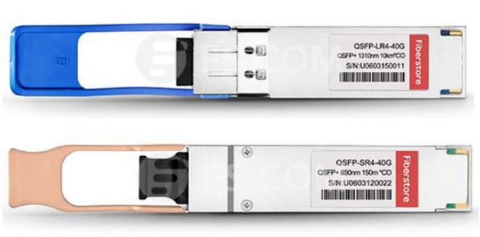
As one of the most widely used QSFP+ transceiver, QSFP-40GE-LR4 transceiver offers an individual 40GbE links that provides better performance with higher bandwidth in the transmission process, instead of SFP transceivers with multiple 10GbE links. The following figure shows an example of QSFP-40GE-LR4 transceiver for your reference.
photo1-20161130
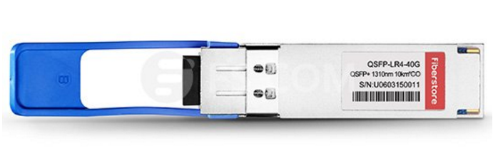
It is easy to learn that the letter “L” in its name indicates long distance, the letter “R” means the type of interface with 64B/66B encoding and “4” stands for four channels. That’s to say, QSFP-40GE-LR4 transceiver is able to support 40G Ethernet network for long distance transmission, at lengths up to 10 kilometers, which consists of a standard pair of single-mode fiber and duplex LC connectors. Meanwhile, it has four channels in each direction to transmit and receive signals, each of which has a 10 Gbps data rate to achieve a total 40 Gbps data rate.
Working Principle of QSFP-40GE-LR4 Transceiver
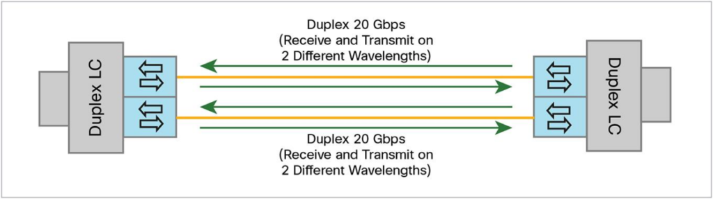
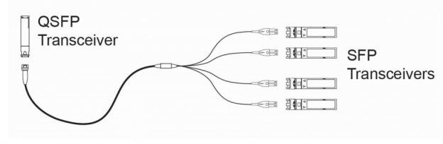
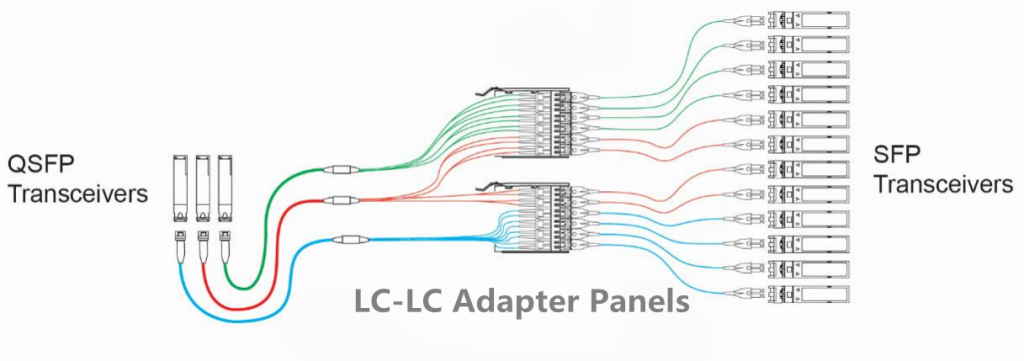
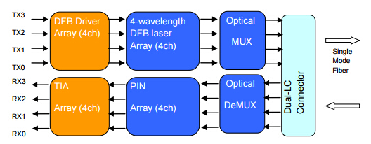
In QSFP-40GE-LR4 transceiver working process, it will firstly convert four inputs channels of 10Gbps electrical signals to four CWDM optical signals, and then multiplexes these four signals into a single channel as a 40Gbps data. Secondly, the data will be propagated out of the transmitter module through single mode fiber and accepted by receiver module. Thirdly, the 40Gbps data will be de-multiplexed into four individual 10Gbps optical signals with different wavelength, and each signal will be transmitted through an individual channel. Finally, these 10Gbps optical signals will be collected by a discrete photo diode, amplified by a TIA, and then outputted as electrical signals.
Compared to 10G SFP transceiver, it is much more complicated in the working process of QSFP-40GE-LR4 transceiver that uses with CWDM technology. To help you better understand its working principle, here offers the whole working process through the following figure that illustrates how QSFP-40GE-LR4 transceivers finish 40G transmission.
photo2-20161130
Guide for Installing QSFP-40GE-LR4 Transceiver
As an indispensable device for deploying 40G Ethernet network, QSFP-40GE-LR4 transceiver can be installed without powering off the system, which provides much convenience and flexibility. However, there are still some points should be paid attention to in the installation process. Here lists the step-by-step procedure of installing QSFP-40GE-LR4 transceiver that may be helpful for you to achieve a smooth 40G migration.
  • Get QSFP-40GE-LR4 transceiver from the antistatic container.
  • Before installing the transceiver, please remove the dust cover from its connector. Meanwhile, if there is a protective pad covering the card-edge connector, please also remove it.
  • Put the antistatic container, dust cover and protective pad away, so that they can be stored cleanly, and found easily if the transceiver need to be uninstalled.
  • Check and remove the rubber dust cover from the port where the transceiver will be installed.
  • Hold the transceiver by its sides, and then insert it into the port on the switch.
  • Lightly slide the transceiver into the port until it is dropped into place.
  • Push up the handle of the transceiver to secure the transceiver in the switch.
Notice: Please pay attention that QSFP-40GE-LR4 transceiver contains Class 1M lasers and it may cause invisible laser radiation. Hence, when the laser connections are unplugged, you should not stare at it which really does harm to your eyes.
Conclusion
Since 40G Ethernet network has become an irreversible trend to achieve higher bandwidth and ensure better performance, there is no doubt that it will finally take the place of 10G Ethernet network. As one of the most commonly used transceiver for 40G migration, QSFP-40GE-LR4 transceiver would be an ideal solution for 40G long distance transmission.

Thursday, November 24, 2016

QSFP-40GE-LR4 and QSFP-40G-SR4 Modules Comparison

Have you ever complained about your slow network speed when you are working in a hurry, watching the most wonderful and interesting part of a movie or doing something else that are delayed by your bad network? Do you want to upgrade your system for higher data transmission speed? Have you ever heard about 40G QSFP+ module which is able to solve your problem? In this post, it will introduce two commonly used types of QSFP+ modules used to upgrade your network from 10G Ethernet to 40G Ethernet, to some extent, avoiding time delay.
40G QSFP+ Modules Overview
Nowadays, there are several solutions designed for deploying 40G Ethernet network, such as, 4 x 10GE Breakout cable, 40G QSFP+ modules or 40G CFP modules. Both of these solutions can achieve the 40GbE with higher capacity. As one of the most commonly used solutions among them, 40G QSFP+ module is a good choice to make the 40G migration. Do you have a good knowledge of 40G QSFP+ modules in the fiber market? At present, there are many variants of 40G QSFP+ modules published to support different applications, defined by IEEE 802.3ba. For instance, QSFP-40GE-LR4, QSFP-40G-PLR4, QSFP-40G-SR4, QSFP-40G-CSR4, etc.
Differences Between QSFP-40GE-LR4 and QSFP-40G-SR4
Among the variants of 40G QSFP+ modules, QSFP-40GE-LR4 and QSFP-40G-SR4 are the most widely applied modules that are designed for different aims. Their features are much different from each other, varying from fiber type to transmission distance. The following will basically analyze the differences between these two modules that may be useful for you to select a proper 40G QSFP+ module.
photo1-20161125
  • Different Fiber Type
As for QSFP-40GE-LR4 module, it has four WDM lanes to transmit and receive signal, which generally works with single-mode fiber. With the advantage of single-mode fiber, it can transmit 40G signals with a long distance. As for QSFP-40G-SR4 module, it has four lanes, which enables high-bandwidth 40G optical links over 12-fiber multimode fiber, operating on a parallel mode. Although it can’t support long distance transmission like QSFP-40GE-LR4 module, it has the ability to carry many kinds of optical signals in 40G Ethernet network.
  • Different Connector
As for the connector, QSFP-40GE-LR4 module always uses duplex LC connectors to connect single-mode fiber, while QSFP-40G-SR4 module is often terminated with MPO/MTP connector used for linking 12-fiber multimode fiber. What should pay attention to is that each kind of connector is easy to be smudged, which may cause a negative effect on the transceiver performance. Hence, no matter which module you choose to deploy 40G Ethernet network, please use a dust plug to protect the connector if the QSFP+ module is not working, so that the connector can be stay in a clean condition.
  • Different Wavelengths
There is no doubt that the light wavelengths are also different used for transmitting signals. As for the former one, it generally uses signals with four different wavelengths, 1271 nm, 1291 nm, 1311 nm and 1331 nm to achieve 40G long distance data transmission. However, the latter one uses the same wavelengths for four lanes: 4 x 850 nm, supporting 40G short data transmission.
  • Different Transmission Distance
It is easy to learn that the letter “L” in QSFP-40GE-LR4 refers to the word “long”, while the letter “S” in QSFP-40G-SR4 stands for “short”. Then how far these two QSFP+ modules can transmit 40G signals? What’s the difference? As for the former one, by using Coarse Wavelength Division Multiplexing technology, it transmit 40G signals through single-mode fiber with four separated or combined 10G SFP+ modules on the other end, with great reach of up to 10 kilometers. However, the latter one can only transmit 40G signals at lengths up to 100 meters on OM3. If it uses OM4 to support the 40G Ethernet network, it can transmit longer, 150 meters.
Conclusion
Have you got any useful information from the post for choosing a suitable QSFP+ module? As above mentioned, QSFP-40GE-LR4 designed with special features is most suitable for 40G long distance transmission, such as, between data-center or IXP sites. If you just need to deploy 40G Ethernet network for short distance, QSFP-40G-SR4 must be an ideal choice with lower price.

Tuesday, November 22, 2016

How Much Do You Know About 40G QSFP BiDi Transceiver?

As we know, there are a variety of QSFP transceivers that have the ability to support 40G Ethernet network with higher capacity and transmission data rate, such as: QSFP-40G-SR4, QSFP-40G-CSR4, QSFP-40G-LR4, QSFP-40G-PLR4, etc. In 40G long distance transmission, there is no doubt that OSFP+ transceivers with duplex LC interface like QSFP-40G-LR4 and QSFP-40G-PLR4 have a high performance. However, for 40G short distance transmission, both QSFP-40G-SR4 and QSFP-40G-CSR4 transceivers are designed complicatedly, requiring 12-fiber MTP/MPO connectors and 12 fibers, which are extremely different from the traditional 10G transceivers. Hence, the cabling infrastructure for the migration from 10G to 40G Ethernet network in short transmission should be changed greatly, which may cost a lot.
Taking the cost into consideration, experts come up with the BiDi technology and design QSFP bi-directional transceiver for 40G short transmission. By using QSFP BiDi technology, 40G Ethernet network can be deployed with the same infrastructure as 10G Ethernet network, thereby a cost saving will be made.
40G QSFP BiDi Transceiver Overview
40G QSFP BiDi transceiver can be also called 40G QSFP bi-directional transceiver, firstly published by Cisco. It is able to transmit 40G signals over duplex multimode fiber optic cables with LC connectors, instead of multi-fibers with MTP/MPO connectors in the traditional 40G QSFP parallel transceiver, which addresses the challenges of cabling infrastructure. In general, there are a pair of duplex MMF cables with duplex LC connectors in one 40G QSFP BiDi transceiver. Each cable offers a 20G channel to transmit and receive 20G signals simultaneously with different wavelengths, achieving a complete 40G data transmission. For better understanding, here offers its working principle in the following figure.
photo1-20161123
Cabling Connection Options for 40G QSFP BiDi Transceiver
When designing 40G Ethernet network with BiDi technology within a given row of cabinets, a Type A-to-B standard LC duplex patch cord is suggested to directly connect two 40G BiDi transceivers. As shown in the following figure, the Type A-to-B standard LC duplex patch cord consists of a blue fiber linked with connector position A on one side and connector position B on the opposite side, and an orange fiber linked in the same way, defined in TIA-568-C.3. This reverse fiber positioning allows a signal to be directed from the transmit position on one end of the network to the receive position on the other end of the network.
photo2-20161123
Interconnect Option for 40G QSFP BiDi Transceiver
How can an interconnect cabling be deployed for 40G BiDi transceiver? As shown in the following figure, we can learn an example of an interconnect link between two bidirectional ports installed in a switch, which includes an MTP-based trunk, MTP-LC cassette modules and LC jumpers. In this interconnect link, both of the LC jumpers connect from the structured cabling patch panel to the electronics ports.
photo3-20161123
There are a lot of advantages by using interconnect cabling for 40G QSFP BiDi transceiver. Firstly, MMF MTP assembly in this interconnect cabling would provide more scalability to accommodate future data rates. Secondly, if you want to do a migration for your network in future, it can be done simply by changing the patch panels on each end of the link, instead of disrupting the cabling infrastructure. What should be pay attention to is that deployment of more permanent links should be taken into consideration when structured cabling is being designing.
Cross-connect Option for 40G QSFP BiDi Transceiver
Other than interconnect cabling, there are two independent structured cabling links that connect two switches in a centralized cross-connect cabling. Here offers an example of the cross-connect cabling approach for 40G BiDi transceiver in the following figure for your reference.
photo4-20161123
This cross-connect cabling is featured with the most flexible network configuration. That is to say, the electronic devices can be installed in various locations throughout the data center, with structured cabling links between the cross-connect location and designated zone cabinets. If you want to install a new equipment in the link, you just need patch cords to make the connection from the equipment to the patch panels.
Conclusion
When making the migration from 10G to 40G Ethernet network in short distance transmission, 40G QSFP BiDi transceiver would be the first choice that requires no changes in the cabling infrastructure. Hence, the cost and required time to deploy 40G Ethernet network could be reduced dramatically. There is no doubt that 40G QSFP BiDi transceiver will eventually displace the traditional 40G QSFP transceiver in a fast and cost-efficient manner.

Friday, November 18, 2016

Overview of 100G QSFP28 Transceiver and Its Cable Assemblies

Have you ever annoyed with your slow network speed that may cause a time delay? Under this circumstance, do you have an urge to smash your computer? In order to deal with this problem that many people may encounter, experts turn to upgrade the system for a higher data transmission rate. For instance, 40G, 100G and even 120G Ethernet network are developed and deployed for higher transmission speed and greater bandwidth, facing the challenge of increasing network needs. Do you have any interest in upgrading your system? This paper will introduce one of the most commonly used 100G transceiver and its cable assemblies for you to flawlessly and smoothly deploy 100G Ethernet network. Thereby, time delays will be avoided when you are working in a hurry next time.
Solutions for 100G Ethernet Network Migration
As we know, installing standard transceivers and cables for 100G Ethernet migration is the most straightforward and efficient method to get a much higher transmission speed. As there are several kinds of transceivers and cables used for 100G Ethernet network, choosing the proper transceiver and its cable assemblies becomes an remarkable issue.
100G QSFP28 Transceiver
At present, there are several 100G transceivers that came into the market, developed for 100G Ethernet applications, such as, CFP, CFP2, CFP4, QSFP28. Compared with the 100G CFP family, QSFP28 has a great improvement in the panel density and also decrease power consumption, which can offer the cost-optimized solutions for 100G migration in a rack or data center. For this reason, it is more popular and commonly used for deploying 100G Ethernet network.
QSFP28 transceiver is the smallest 100G form factor transceiver with the same size as QSFP+ Transceiver used for 40G Ethernet applications. Meanwhile, it is also the optimized transceiver with the lowest power consumption among those 100G transceiver. When working and interconnecting, the data transmission speed of its four channels for differential signals will vary from 25 Gbps up to potentially 40 Gbps, which will finally achieve 100Gbps data rate.
In generally, 100G QSFP28 transceivers can be divided into two types, QSFP28-SR4 transceiver and QSFP28-LR4 transceiver, as shown in the following figure. As for QSFP28-SR4 transceiver, it is designed for supporting 100G Ethernet network at lengths up to 100 meters through multimode fiber. It works with non-standard MPO (multi push-on/pull-off cable) connectors which make some of the cost savings for the transceiver. As for QSFP28-LR4 transceiver, it has the ability to support connections up to 10km over single-mode fiber, with standard LC connectors and the existing structured LC cabling.

Is there any transceiver to support 100G Ethernet network that can transmit signals longer than 10 km? With the invention of DWDM QSFP28 PAM4, the answer is yes. To handle 100G Ethernet network with longer distance, through unremitting endeavor, experts finally make some breakthroughs in transceivers with DWDM capabilities and develop one of the most significant transceiver, DWDM QSFP28 PAM4, that can transmit signals at lengths up to 80km. However, the working principle of DWDM QSFP28 PAM4 is much more complicated than basic QSFP28 transceiver that requires amplification for even very short distances and needs dispersion compensation for any distance over 5 or 6km.
100G QSFP28 Cable Assemblies
In comparison with QSFP28 transceiver, QSFP28 cable (DAC or AOC cable) is much more convenient and cost-efficient to support 100G Ethernet network by directly connecting 100G equipment. What’s more, using a single cable assembly can solve many problems that caused by association with connectors.
As for its classification, there are basically two types of cable assembly, QSFP28 AOC and DAC (see in the following figure). QSFP28 DAC is suitable for applications within 15m transmission distance, while QSFP28 AOC can transmit signals much longer, at lengths up to 70m. Hence, you can select the proper cable assembly according to the transmission distance your network requires.

Conclusion
From the above information, we can learn that QSFP28 modules offer the best solution for 100G migration with the lowest power consumption at present. As for QSFP28 transceiver and it cable assemblies, you can choose it just on the basis of the transmission distance your network requires. As the development of fiber optic technology will never stop, there is no doubt that more and more transceivers and cable assemblies would be designed for much higher transmission speed, meeting the increasing network needs.

Friday, November 11, 2016

In-Depth Study of SFP, BiDi SFP and Compact SFP

Tremendous progress has been made over the past few decades with advent and development of Ethernet network. During this period, a variety of optical fiber transceivers have been designed and manufactured by several optical fiber manufacturers for meeting the requirements of Ethernet network, such as, Cisco gigabit SFP, NETGEAR GBIC. As one of the most pivotal component among these optical fiber transceivers, SFP modules play an important role in Ethernet network that largely made the GBIC modules obsolete and greatly accelerated the development of optical fiber transceivers. To better understand SFP modules, this article will make a brief introduction of SFP transceiver and study three kinds of SFP modules, SFP, BiDi SFP and compact SFP.

SFP Transceiver Overview

SFP transceiver is one of the variation of the GBIC transceiver, which can also be called small form-factor pluggable transceiver or mini-GBIC. Its function is the same as GBIC transceiver, but it has a smaller form factor and higher performance than GBIC transceiver. Due to its smaller size and higher speed, it is largely used in the field of telecommunication and data communication, instead of GBIC transceiver.

SFP transceiver is consisted of a transmitter on one end and a receiver on the other end which are designed to work separately. In data transmission process, the transmitter will convert the electrical signal into light signal and transmit the light signal to the receiver. Once the receiver receives the light signal, it will convert the light signal into electrical signal again to finish the data transmission.

Comparative Analysis of SFP, BiDi SFP and Compact SFP

As technologies drive to maturity stage, SFP transceivers become diversified, designed for different aims with various feature. Meanwhile, the functions of these SFP transceivers are improved greatly to meet increasing demands of network. The following will make a comparative analysis of three commonly used SFP transceivers, SFP, BiDi SFP and compact SFP, which may help you make a decision when selecting proper SFP transceiver for your network.

Structural Differences

It is well known that a common SFP transceiver is usually with two ports, TX port and RX port. The TX port is to transmit the signal, while the latter one receives the signal. Clearly different from the common SFP transceiver, BiDi SFP transceiver has only one port, working with an integral WDM coupler to transmit and receive signals. Its transmission is also done through a single strand fiber. As for the compact SFP, it is much more complicated than the previous ones. In fact, it is designed as a 2-channel BiDi SFP that integrates two BiDi SFP in one SFP module. That’s to say, there are two ports in a compact SFP to transmit and receive signals, which is the same as the common SFP. To better know about the structural differences among the three kinds of SFP modules, you can take the following figure as reference.

Connection Method Differences

In general, all SFP transceivers must be used in pairs. However, since the structure of these three kinds of SFP modules are different, they should be connected to fiber equipment in different methods.

As for the common SFPs, when connecting two SFPs for data transmission, you should ensure that they works with the same wavelength together. For example, if you use a 850nm SFP at one end, a 850nm SFP on the other end is also required for the whole transmission. For the detailed connection of common SFPs, it is presented in the following figure for your reference.

As for BiDi SFP, it has the ability to transmit and receive signals with different wavelengths, but you should connect two BiDi SFPs with opposite wavelengths together. Hence, the transmission can be processed correctly. As shown in the following figure, if you use a 1310nm-TX/1490nm-RX BiDi SFP at one end, a 1490nm-TX/1310nm-RX BiDi SFP should be used on the other end.

As for the compact SFP, it usually transmit signals with 1490nm wavelength and receive signals with 1310nm wavelength. That is, if you choose the compact SFP for your network, two 1310nm-TX/1490nm-RX BiDi SFPs should be connected through single-mode fibers as shown in the figure below.

Conclusion

As one of the most basic modules, SFP transceivers is of epoch-making significance in the history of optical fiber transceivers. And the three types of SFP transceivers mentioned in this article with various features are suitable for different application, which should be connected with specific methods. Hope the information in this article can guide you to select the proper SFP modules for your network.

Tuesday, November 8, 2016

Selecting the Right 40G QSFP+ Transceivers and Cables

It is well known that telecommunication equipment experts have designed and developed a variety of fiber optical products to meet the increasing requirements of our network. As one of the most important components among these fiber optical products, fiber optic transceiver has caused more and more value that has been diversified to achieve higher and higher transmission speed and smaller and smaller size, such as, GBIC, SFP, XFP, SFP+, QSFP+, etc. In this post, it will give a detailed selection guide to QSFP+ transceivers and their cabling options, both of which are very popular and commonly used in building 40G Ethernet network.

Commonly Used 40G QSFP+ Transceivers

QSFP+ transceiver is also known as Quad Small Form-factor Pluggable transceiver, which is designed for 40G Ethernet network. Generally, it has four channels of data in one pluggable interface and each channel has the ability to transmit the data at 10Gb/s rate. Thereby, it can support 40G Ethernet network. The following will introduce three commonly used QSFP+ transceivers, 40GBASE-SR4, 40GBASE-SR-BiDi and 40GBASE-ER4, helping you choose the most suitable one for your network.


40GBASE-SR4 Transceiver

40GBASE-SR4 transceiver can support 40G Ethernet network by transmission through muldi-mode fiber (MMF), which is able to transmit signals at lengths up to 100 meters through laser-optimized OM3 and 150 meters through OM4. The high-bandwidth 40G optical network is set up through 12-fiber parallel fiber that terminated with MPO/MTP multi-fiber female connectors, occupying 4 fibers for sending signals, 4 fibers for receiving signals and 4 fibers wasted. In addition, it can also be applied in a 4x10G mode for interoperability with 10GBASE-SR interfaces, with no change in transmission distance.

40GBASE-SR-BiDi Transceiver

40GBASE-SR-BiDi is a pluggable optical transceiver with a duplex LC connector interface for short distance data communication and interconnect applications, also working with MMF. Each QSFP 40GBASE-SR-BiDi transceiver is composed of two 20G transmitting and receiving channels in the 832-918nm wavelength range, which enables an aggregated 40G link over a two-strand MMF connection. Compared to 40GBASE-SR4 transceiver, this kind of transceivers only requires a duplex LC patch cord to accomplish 40G transmission at lengths up to 100 meters over OM3 and 150 meters over OM4 that works in a much more straightforward transmission mode. In short, 40GBASE-SR-BiDi transceiver gives the users a big convenience to build their 40G Ethernet network.

40GBASE-ER4 Transceiver

Clearly different from the previous transceivers, 40GBASE-ER4 works over single mode fiber (SMF) to finish 40G communication, supporting the link at lengths up to 40km with duplex LC connectors. There are four kinds of wavelengths in the 1310nm range used to transmit signals, which will be multiplexed and demultiplexed in the transmission process. If you want to build your 40 Ethernet network for long distance transmission, this kind of transceivers must be a good choice.

Commonly Used 40G QSFP+ Cabling Options

In general, there are three commonly used 40G QSFP+ cabling options, QSFP to QSFP copper direct attach cables (DACs), QSFP to QSFP active optical cables (AOCs), QSFP to four SFP+ breakout cables as shown in the following figure. To better understand the features of these cabling options, you can take the listed information as reference.


As for QSFP to QSFP Copper DACs and QSFP to QSFP AOCs, both of them are developed for short distance transmission by providing a flexible solution for connection within racks and across adjacent racks. In contrast to DACs, AOCs are much thinner and lighter that facilitates the cabling. Since AOCs enable efficient system airflow and have no EMI issues, there is no doubt that AOCs have a higher performance than DACs when designing 40 Ethernet network.

As for QSFP to four SFP+ breakout cables, they are available in two types: QSFP to four SFP+ copper breakout cables and QSFP to four SFP+ active optical breakout cables, which can be in 1m, 2m, 3m, 5m, 7m and 10m. By offering more space for data centers with low cost, this kind of 40G QSFP+ cabling option becomes a highly cost-effective interconnect solution to set up 40 Ethernet network.

Conclusion

From this post, we can conclude that 40GBASE-SR4 and 40GBASE-SR-BiDi transceiver are commonly used in short distance 40G transmission, while 40GBASE-ER4 can support 40G transmission with long distance. As for the 40G QSFP+ cabling options, you can choose the most suitable one to match your network. Hope the information in this post would be helpful for your 40G QSFP+ optics selection.

Thursday, November 3, 2016

How to Ensure MPO/MTP Systems Work with Correct Polarity?

With the appearance and development of 40/100G Ethernet network, MPO/MTP technology is developed for migrating to 40/100GbE, which is of high density, flexibility and reliability with scalable, upgradeable properties. Do you want to upgrade your system to 40/100G Ethernet network? Are you familiar with MPO/MTP technology? Do you know how to ensure MPO/MTP systems work with correct polarity and why the polarity of the connections using multi-fiber MPO/MTP components from end-to-end should be assured?
Generally, MPO/MTP technology is to pull just one single cable with multiple fibers, which is deployed for multi-fiber applications. When using the technology in 40/100G Ethernet network, only maintaining a correct polarity across the fiber network, could you ensure that the signal transmitted from any of the active equipment can be directed to the receive port of the next active equipment. In order to ensure MPO/MTP systems work with correct polarity, experts develop three methods that will be presented in this paper.
Three Polarization Methods with Corresponding MPO/MTP Cables
For ensuring proper polarity, experts put forward three polarization methods, which are defined by TIA 568 standard and named as Method A, Method B and Method C. As different polarization methods employ different MPO/MTP trunk cables to connect the fiber network, there are three types of MPO/MTP truck cables with different structures called Type A, Type B and Type C used for the three different connectivity methods respectively. The following will introduce the detailed information of each method with its corresponding truck cable.
Polarization Method A with Type A Trunk Cable
To better understand Polarization Method A, the Type A Trunk Cable should be first introduced that is also referred to as straight cable. It is a straight through cable with a key up MPO/MTP connector on one end and a key down MPO/MTP connector on the opposite end, which makes the fibers at each end of the cable have the same fiber position as shown in the following figure. For instance, the fiber located at position 1 (P1) of the connector on one side will arrive at P1 of the other connector, and the fiber located at P12 on one side will arrive at P12 on the other side.
As for Polarization Method A, it always works with the Type A trunk cable that is designed to connects MPO/MTP modules on each side of the link. The connectivity Method A is also shown in the following figure for your reference.
photo20161104a
Polarization Method B with Type B Trunk Cable
In Polarization Method B, Type B truck cable is used to connect the two modules on each side of the link. Clearly different from Type A trunk cable, Type B trunk cable uses two key up connectors on both ends of the cable, which is known as reversed cable. This mating structure results in an inversion, which means the fiber positions are reversed at each end. For example, the fiber at P1 of one end is mated with the fiber at P12 of the opposing end. From the following figure, you can learn the fiber sequences of a 12 fiber Type B cable and the connectivity Method B.
photo20161104b
Polarization Method C with Type C Trunk Cable
Compared with the previous methods, Polarization Method C is more complicated that works with Type C trunk cable. Type C trunk cable is used for connecting MPO/MTP modules one each side of the link which can be also called pair-reversed trunk cable. You can study the connectivity Method C in the following figure.
Just like Type A trunk cable, Type C trunk cable also has one key up connector and one key down connector on each side. However, it is more sophisticated because each adjacent pair of fibers are designed to flip at each end. That’s to say, the fiber at P1 on one end of the cable will be shifted to P2 on the other end and the fiber at P2 on one end will be mated with P1 on the opposite end, etc. To help you better understand the fiber sequence of Type C cable, you can take the following figure as reference.
photo20161104c
Conclusion
From this paper, we can conclude that there are three polarization methods which are developed to ensure MPO/MTP systems work with correct polarity, and each polarization method has its own trunk cable to connect the modules in each end of the link. If you want to upgrade your system to 40/100G Ethernet network, you can choose the most suitable method for assuring the correct polarity in your fiber network, which will make your system work great.

Tuesday, November 1, 2016

How to Connect 10G SFP+ and 40G QSFP+ Transceivers?

Introduction
As the requirement of optical network is unremittingly increasing to meet the market needs, the types of fiber optic transceivers become diversified to achieve the goal of faster and faster data transmission rate and smaller and smaller size, such as: GBIC, SFP, SFP+, QSFP+, etc. There are too many types of transceivers that you can choose for establishing your network. Have you ever wondered how to use them for your network? Can two different transceivers be connected? To help you better understand the transceivers, this paper will introduce the connections between two different, commonly-used transceivers, small form-factor pluggable (SFP+) transceiver and quad small form-factor pluggable (QSFP+) transceiver.
It is well known that a 10G SFP+ transceiver is usually a 2-fiber duplex link, while 40G QSFP+ transceiver can be either an 8-fiber parallel link or a 2-fiber duplex link. Can a 40G QSFP+ transceiver with an 8-fiber parallel link be connected with the 10G SFP+ transceiver? If yes, how to connect them?
Three Connection Methods for the Two Transceivers
Considering that QSFP+ transceiver is 40G interface and SFP+ is 10G interface, four SFP+ transceivers must be required if it is possible to be connected with a QSFP+ transceiver. In order to achieve 40G transmission between a 40G QSFP+ transceiver and four 10G SFP+ transceivers, experts came up with three useful methods: direct connectivity solution, interconnect solution and optimized solution.
Direct Connectivity Solution With MTP-LC Harness Cable
When using the direct connectivity solution to connect QSFP+ transceiver and SFP+ transceivers, you need an eight fiber MTP-LC harness cable to maintain the proper polarity. The harness cable consists of four LC duplex connectors on one end to connect four SFP ports, one MTP connector on the other end to connect the single QSFP port and specifically paired fibers as shown in the following figure. In addition, this solution of connection between QSFP+ and SFP+ transceivers is only suitable for short distance transmission, for instance, within a given row or in the same rack/cabinet.
photo1
Interconnect Solution With MTP-LC Module
The interconnect solution is also suggested to be used in short distance applications, where the connection takes place within a given row of racks/cabinets. When this method is being used to connect the QSFP+ and SFP+ transceivers, a MTP-LC module is required to make a link to connect the QSFP+ transceiver in one side and four links to connect the SFP+ transceiver in the other side. Besides, a Type-B non-pinned MTP to non-pinned MTP cable will be used between MTP-LC module and QSFP transceiver. You can learn the details of this solution in the following figure.
photo2
What should be noted is that this solution does present some disadvantages. As shown in the figure above, the ports 5 and 6 of the module are not being used that may reduce the patch panel density. Since these two ports are unused and dark, it may also cause some confusion when the connection occurs.
Optimized Solution With LC-LC Adapter Panels
Unlike the interconnect solution, the optimized solution has eliminated the disadvantage of dark fibers or ports, which also allows full patch panel density in the connection process. From the following figure, you can learn that the MTP-LC module for the connected function is replaced with the LC-LC adapter panel and the Type-B jumper is also replaced with an eight-fiber harness in the optimized solution. If you want to choose this method to connect QSFP+ and SFP+ transceivers, two LC-LC adapter panels will be required for every three 8-fiber harnesses. Hence, all ports on the LC-LC adapter panels will be used. Besides, you should also note that this solution can be also used for deploying when there is a short distance between active components (within the same row).
photo3
Conclusion
The above connection methods between QSFP+ and SFP+ transceivers are appropriate for short distance transmission. Since there are special features of each method, you can choose the most suitable one for your network.