Friday, February 24, 2017

Breakout Panel Solutions for 10G to 40/100G Migrations

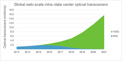
Although most data centers still deploy the 10 Gigabit Ethernet (GbE) networks, the 40/100 GbE networks have gradually become new and preferable options for them, which can be also reflected from the greatly increasing shipments of 40/100G optics. As the data of migration from 10G to 40/100G constantly grow, how to connect the 40/100G device with the existing 10G device in a fast and cost effective manner becomes a particularly vital concern of data center managers. To deal with this issue, experts come up with the MPO pre-terminated optical fiber cabling that is an ideal solution for smooth migration from 10G to 40/100G. In this paper, the breakout panel, a new kind of MPO pre-terminated product, will be studied that facilitates the 10G to 40/100G migration and enables simpler and more efficient network management.
Breakout Panel for 10G to 40G Migration
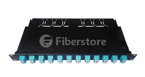
The breakout panel used for 10G to 40G migration can be referred to as 40G breakout panel or 40G QSFP+ breakout panel, available in both single-mode and multimode versions with the color coded adapters. Just taking the 1RU 40G breakout panel as an example, there are 12 standard MTP connectors (8-fiber) elite to 48 duplex LC connectors, which can build up to 12-group breakout links for the 10G to 40G migration. What’s more, the 40G breakout panel can be designed with up to 96 ports for meeting the high density cabling demands, supporting 480G at most. In short, this kind of breakout panel is a good choice for making a high-performance and reliable straight connection from 10G to 40G.
40G Breakout Panel
Breakout Panel for 10G to 100G Migration
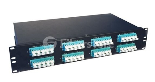
We are used to choose the 24-fiber MTP to 10 duplex LC breakout cable to finish the 10G to 100G connection. When it is working, there are 20 fibers in the MTP side to transmit and receive 10G signals and 2 top and bottom fibers on the left and right unused, achieving the 10G to 100G connection. However, there is a serious problem caused if this kind of breakout cable is used for the application, which may increase cable congestion, clutter, tangling and confusion. In order to improve the efficiency and manage the cables better, the breakout panel used for 10G to 100G migration is published with more complicated design than 40G breakout panel. It is fitted with 8 24-MTP (20 fibers used) elite to 80 duplex LC in 1RU panel, which is able to deploy 8 groups of 10G to 100G connections in a simple, efficient and well maintained manner.
100G Breakout Panel
Significance of Breakout Panel
The breakout panel combines the advantages of MPO pre-terminated breakout cabling and compact patch panel that can not only solve the cable congestion issue but also save space and cost. Except that, it has various kinds of cabling standards that are available for the 10G to 40/100G migrations. In short, the breakout panel offers a perfect solution for the migration from 10G to 40/100G high density network. To better know the advantages of breakout panel, the following figure illustrates how does a 40G breakout panel work for the 10G to 40G application.
40G breakout panel for the 10G to 40G application
From the figure above, we can learn that the 40G breakout panel is very suitable for the 10G to 40G migration that features MTP interface to connect the 40G QSFP+ module and duplex LC interface to connect the 10G SFP+ module. With the use of 40G breakout panel, the 10G to 40G migration will be easily achieved, greatly meeting the requirements of high density and avoiding the cable congestion issue.
Conclusion
In order to gain higher network speed and larger bandwidth, the 40/100G network market is booming in recent years, which means the cabling network will be more and more complicated. In order to address the cable congestion issue and make the 10G to 40/100G migration in a smooth, efficient and well maintained manner, the 40G and 100 breakout panel are highly suggested. Besides, here offers an article that has more information about the breakout panel solutions.

Tuesday, February 21, 2017

Why Not Deploy 100G Ethernet Network?

Transceivers like Cisco SFP+, Juniper SFP+ are always used for deploying 10G Ethernet network, while transceivers like Cisco QSFP+, Juniper QSFP+ are chosen to deploy 40G Ethernet network if the network capacity and speed provided by the 10G Ethernet network are not able to meet our need. However, as our requirements for larger network capacity and higher network speed never stop, what should we do when the 40G Ethernet network can not satisfy our requirements any more? The answer is 100G Ethernet network, which is just a preferable solution to accelerate network speed for those bandwidth-hungry applications.

Benefits from 100G Ethernet Network

Since the 100G Ethernet network has been designed and put into use, the need for deploying 100G Ethernet network is always on the rise that can be learned from the following figure. What’s more, it is predicted that over half of the data center will migrate their systems to 100G Ethernet networks in near future. What makes the 100G Ethernet network so popular? What can we benefit from it? Let’s explore the advantages of deploying 100G Ethernet network.

100G optical transmission vs. 40G optical transmission

In general, the advantages of 100G network can be concluded in four aspects. First and foremost, 100G network has the merits of expansion and scalability which is designed to support the reliability, manageability and flexibility of modern network while prepared for the bandwidth and speed requirements of future network. Due to allow for network changes in the future, 100G network can be still regarded as future-proofing network. Secondly, as a cost effective solution to greatly expand the network capacity, it features unsurpassed bandwidth and can be available at a compelling price. Thirdly, it is the first choice across long-haul networks for its large capacity and fast network speed that can be customized, optimized, and easily expanded to meet the future use. And finally, with the popularity of network transition from 10G/40G to 100G network, the 100G network technology is continuing to mature, which undoubtedly drives down the cost of 100G devices, such as QSFP28 transceiver modules and QSFP28 cables.

QSFP28 Transceiver—an Ideal Solution for 100G Ethernet Network
At present, there are several kinds of 100G transceivers, such as, QSFP28, CFP, CFP2 and CFP4, designed for different applications where the 40G transceivers can’t meet the requirements any longer. Among these 100G transceivers, the QSFP28 transceiver is the most widely used one which should be attached importance to for owning a fast, smooth and stable 100G network.

Similar to the QSFP+ transceiver that features four 10Gbps lanes to finish 40G transmission, the QSFP28 transceiver is also designed with four lanes, each of which transmits 25Gbps signal to achieve the whole 100G transmission and even supports the signal up to 28Gbps with an upgrade electrical interface. Meanwhile, the footprint and faceplate density of the QSFP28 transceiver are the same as those of the QSFP+ transceiver, but its advantages of higher density, lower power consumption and lower price per bit make itself superior to the QSFP+ transceiver.

FAQ for Using QSFP28 to Deploy 100G Ethernet Network

When using QSFP28 to deploy 100G Ethernet network, you may be confused about some questions. For instance, why we should choose this kind of 100G transceiver? What is the difference between QSFP28 and QSFP+ transceiver? And how many QSFP28 transceiver modules can be fitted into one switch? The following will give you the answers for these problems, which may be useful for you to deploy a fast, smooth and stable 100G network.

Why we should choose QSFP28 transceiver to deploy 100G network? In contrast to other 100G transceivers like CFP family, QSFP28 has greatly increased the panel density and decreased power consumption which can save cost a lot. For example, the increase in density is even more dramatic when compared to other 100Gbps form factors, such as, 450% versus the CFP2. For this reason, it is highly recommended to use QSFP28 to deploy our 100G network.

What is the difference between QSFP28 and QSFP+ transceiver? These two transceiver modules have the same size form factor and the number of ports, while the lane speeds of QSFP28 transceiver are increased from 10 Gbps to 25 Gbps. Hence, the QSFP+ transceiver is always used for 40G transmission with the four 10 Gbps lanes, but QSFP28 transceiver features four 25 Gbps lanes to achieve 100G transmission.

How many QSFP28 transceiver modules can be fitted into one switch? Just taking the one rack-unit (RU) switch as an example, it generally accommodates up to 36 ports for QSFP28 transceiver modules. In addition, there are also many other kinds of transceivers and cables (DACs and AOCs) can be plugged into these ports.

Conclusion

100G Ethernet network is definitely a preferable solution to accelerate network speed and expand the network capacity, which is strongly suggested for those bandwidth-hungry applications. Meanwhile, QSFP28 transceiver module is the ideal choice to deploy the 100G network for large scale data centers, as well as future network expansions, which features higher port density, lower power consumption and lower cost. Since there have been several kinds of QSFP28 transceiver modules available on the market for different application, if you want to choose one proper QSFP28 transceiver for deploying your 100G network, you can visit this article that shows the basic knowledge of common QSFP28 transceiver modules.

Thursday, February 16, 2017

Brief Introduction of Some Common Cable Lacing Bars

Various kinds of cable management tools like wire ties, J-Hooks, and cable lacing bars were designed and came into the market to meet the growing requirements of high density network, which enables better cable management. Among this tools, the cable lacing bar is one of the most common used cable management tool that can well manage the cables for rack or enclosure systems and keep the network in good performance and high effectiveness. In this paper, it will mainly introduce the knowledge of cable lacing bar and some common types of cable lacing bars, which is very useful for making the decision about which one should be chosen to manage cables.
Cable Lacing Bar Overview
Cable lacing bar is also referred to as lacer bar, generally made of metal material, which usually works with the wire ties or adjustable clips for providing support and management to the patch cables in rack or enclosure systems. As one of the most popular cable management tools, it only occupies 1/3 to 2/3 of a rack space and can secure and manage up to 24 cables in 1 RU that can greatly save space for installing other necessary devices. Meanwhile, the routing of cables will be also improved to a more neat one if the cable lacing bar is putting into use. Except that, it can stably control the bend radius of the patch cables so that these cables can not be damaged unexpectedly. As for its application, it can be mounted to the rear of a standard 19" rack or cabinet, or behind a patch panel, for better cable management.
Six Common Cable Lacing Bars
Since there are basically six common cable lacing bar, round lacing bar, round lacing bar with offset, square lacing bar, L-shaped lacing bar, 90 degree bend lacing bar and horizontal lacing panel, available on the market and designed for specific cabling networks, the following will offer the information of these cable lacing bars for helping you choose the most suitable one to manage the patch cables in your network. Hope the information below would be useful for you.
Round Lacing Bar
Round lacing bar features flattened ends, which diameter is 1/4 inch. If you want to know its appearance, you can learn it from the following figure. As for its application, if a small profile is required and small or individual horizontal cable runs in your network, you are highly recommended to use this kind of cable lacing bar for cable support and management.
round lacer bar
Round Lacing Bar with Offset
Similar to the round lacing bar, the diameter of the round lacing bar with offset is also 1/4 inch, and its ends is flattened, too. As for its structure, it is shown in the following figure. Compared to the previous one, it can offer 1.5" offset or 4" offset for better cable management. In details, when lacing small bundles or individual cable off the rear of equipment, patch panels and other components, you can choose the round lacing bar with appropriate offset based on the distance from the rear of equipment to the rack rail and use it to relieve cable stress from the connections.
Round Lacing Bar with Offset
Square Lacing Bar
Square lacing bar still features 1/4" diameter rod and flattened ends, as shown in the figure below. It is a good choice for lacing cables vertically or horizontally, while also recommendable for cable routing at the rear of equipment.
Square Lacing Bar
L-shaped Lacing Bar
L-shaped lacing bar is much stronger than other kinds of lacing bars, which has fixed lacing points to support more patch cables. Unlike the round lacing bar with offset, this kind of lacing bar is available in 2", 4" and 6" offset to relieve cable stress. Its appearance is just like the letter L as its name implies, which can be also learned from the following figure.
L-shaped Lacing Bar
90 Degree Bend Lacing Bar
90 degree bend lacing bar, a special kind of lacing bar, which has some features in common with the offset round lacer bar, that provides full-width support to the cables and clearance around the components to extend past the rear rack rail (16-5/8" open width).
90 Degree Bend Lacer Bar
Horizontal Lacing Panel
Horizontal lacing panel is an ideal solution for the application where a lot of cables or mounting devices should be laced. In contrast to the previous cable lacing bars, it has the advantages of large flange, numerous cable tie points and more surface for mounting.
Horizontal Lacer Panel
Conclusion
Cable lacing bar is a useful and cost effective cable management tool for rack or enclosure systems that are always works with the wire ties to support and manage the patch cables. It is able to avoid cable strain especially when trying to run cables from one side of the enclosure to the other, which also greatly saves space and highly improves the network to a more neat one. Any need for these kinds of cable lacing bars or wire ties can be satisfied at FS.COM who always offers the solutions for high density applications.

Sunday, February 12, 2017

Wide-base J-Hook for Supporting Cat 5e Patch Cords

Background Introduction
When holding and pulling the Cat 5e patch cords to deploy high density network, you should do some special handling for them, so that they can be more supported than the less-sensitive voice-grade cables used in traditional cable pulls. Why it is required? It’s because if you just use the narrow-base fasteners like cable ties and bridle rings to hang and support the cable bundles, the stress points will be created and the bend radius of Cat 5e patch cords will be exceeded. Under this condition, the Cat 5e patch cords are easy to be damaged by any overbending, twisting or stressing that may cause your network failure.
But how to make the Cat 5e cabling for ensuring the performance of the high density network? In fact, there are two solutions put forward to deal with the issue, the horizontal cabling tray and the J-Hook. Considering that the horizontal cabling tray solution is more expensive and time-consuming to install than the J-Hook one, so it is not recommendable at all. As for the J-Hook solution, it is much more practical, specially designed for high density network cabling. Let’s study the main features and advantages of the J-Hook solution and learn how to use the wide-base J-Hook for supporting the Cat 5e patch cords for better network cabling.
J-Hook Overview
J-Hook is a special kind of fastener, usually made of galvanized steel but sometimes of plastic polymers, which can be installed in both indoor and outdoor high density application for supporting more than one Ethernet patch cable or cable bundle. It is easy to learn that its structure is like the letter “J” from its name, while from the following figure it is better to know its “J” structure that features a wide base with smooth and rounded corners and 90-degree angle bracket. This design is able to eliminate the potential for snags during installation, while preventing the development of stress points where the cable bundle is supported. As for its application, J-Hook can be easily and fast installed in various environments, such as beams, "C" or "Z" purlin, acoustical trees, drop wires, decks, and ceilings. In short, J-Hook offers an alternative solution to the cabling tray which is very cost effective to secure the cables like Cat 5e, Cat 6 and Cat 6a patch cords in the whole network.
J-Hook Cable Suport
How to Use the Wide-base J-Hook for Supporting the Cat 5e Patch Cords?
As mentioned above, the wide-base J-Hook is specially designed to support the Ethernet patch cables. But how to use it to achieve the aim? Is it difficult to be installed? Let’s take the step by step procedures about using the wide-base J-Hook for supporting the Cat 5e patch cords in the following text as an example.
  • Firstly, attach the proper J-Hook--whether for wall, stud, beam, flange or drop-wire mounting--to the supporting structure. Space the J-Hooks to fall every 4 to 5 feet.
  • Secondly, put the Cat 5e patch cords in the J-Hooks. Ensure that the cable sag between the J-Hooks is less than 12 inches at midspan. If the sag is more than 12 inches, then you should add additional J-Hooks to support the cables. (Cable sag in actual application will rely on the number of cables in each bundle and the weight of the cables.)
  • Thirdly, if the J-Hook is able to work with the cable tie, you are suggest to use the prepunched holes in the J-Hook to install the tie. This prevents the Cat 5e patch cords from lifting. Be sure that the cable tie does not put pressure on the cables which may cause the geometry distortion of the cables.
  • Finally, check the whole installation and confirm there is no problem in the installation. Meanwhile, please ensure that the overall appearance of installed cable is neat.
Note: During the installation process, you should keep the cable-pulling tension constant and keep it below the EIA/TIA-568A specification for the Cat 5e patch cords.
Conclusion
J-Hook is a good solution to deploy and manage the Ethernet patch cables like Cat 5e patch cords in the high density network, which enables neat and high performance network, and money and time savings. In contrast with other cable management tools, it requires fewer materials and can be easier and faster to be installed. Hence, if choosing the J-Hook solution to manage the cables in high density environment, you can save a lot of time and money.

Wednesday, February 8, 2017

In-Depth Look at Stranded and Solid Ethernet Cable

As we know, Ethernet patch cable can be divided into unshielded and shielded Ethernet cable (also referred to as UTP and STP cable) according to whether it is to be shielded. Except that, the Ethernet patch cable can also be divided into into stranded and solid Ethernet cable that have different features and advantages. Since these two kinds of Ethernet patch cables are very commonly used, do you have a good knowledge of them? When designing your wired network, have you ever hesitated over making a decision about which one should be choose to deploy your network? In this paper, it will mainly make an in-depth study of the stranded and solid Ethernet cable and seek the most proper one for you to manage your cabling network.
Stranded and Solid Ethernet Cable Overview
The stranded Ethernet cable is made up of multiple smaller strands of wires which are twisted together to form a single conductor, typically used for patch cords/cables connecting workstations, from wallplate outlet to patch panel and from patch panels to individual workstations. While the solid Ethernet cable is just composed with the single solid strand of copper for each of the 8 conductors that is designed for permanent and semi-permanent installations in longer distance horizontal and backbone cable runs, PoE (power over Ethernet), and HD applications. To better understand the difference between the stranded and solid Ethernet cable, the following figure shows their internal structures.
Stranded vs. Solid Ethernet Cable
Stranded and Solid Ethernet Cable Comparison
From the figure above, we can easily learn that the stranded Ethernet cable consists of multiple twisted strands of insulated bare copper conductors, but the solid Ethernet cable features solid insulated bare copper conductors. Why the strands of wires in the stranded Ethernet cable are designed to be twisted together? Compared to the non-twisted solid Ethernet cable, can the stranded Ethernet cable benefit from this special design?
In fact, the twisted feature of the stranded Ethernet cable is designed with the aim of protecting the cable from bending or damage, which provides high flexibility. For a given conductor length of the cable, the more times each strand is twisted around the central conductor, the higher the overall flexibility of the cable and the better the protection will be. Considering that the internal structure in each type of the stranded Ethernet cable are different, if you want to choose a highly flexible stranded Ethernet cable to make your cabling network, you’d better to choose a specified one to meet the detailed requirement of your network.
As for the solid Ethernet cable, what are its features and advantages, and when and where should or shouldn’t it be used for cabling network? In general, the conductor of this kind cable usually features the diameter varying from 22 and 24 AWG wire gauge. For instance, the solid Cat 6 Ethernet cable utilizes 23 AWG copper wires that is larger but more proper for the new and emerging fast Ethernet applications than the solid Cat 5e Ethernet cable with 24AWG wire gauge. As the solid Ethernet cable is easier to be broken if it is over-flexed, bent, or twisted beyond the cable recommended specifications, all the solid Ethernet cables should be seriously made with the minimum bend radius for performance standards and correctly installed to maximize the performance of the cable. Besides, it is not recommendable for daily connecting use due to its fragility, but suitable for permanent and semi-permanent applications.
Conclusion
With the diversity and popularity of the Ethernet patch cable for Ethernet network, there is no doubt that the copper transmission medium will support higher and higher data transmission rate and frequency. Like the two Ethernet patch cable mentioned above, the solid Ethernet cable is less flexible but cheaper than the stranded Ethernet cable, which also performs not so good as the latter one. If you want to make a permanent and semi-permanent cabling, then the solid Ethernet cable is a good choice for you that will save you a lot. But if your cabling network is deployed for daily use, then you are strongly suggest to choose the stranded Ethernet cable.

Sunday, February 5, 2017

Cat 6a Shielded Cable vs. Cat 6a Unshielded Cable

As the need for high bandwidth and fast data transmission rate is on the rise, the deployment of 10G Ethernet network becomes much more common and popular than ever before. Cat 6a cabling, the most proper cabling infrastructure for deploying 10G Ethernet network, is designed under this trend and promptly acquiring popularity for offering the throughput that many users now demand. Do you also plan to deploy 10G Ethernet network with Cat 6a cabling? Since there are Cat 6a shielded cable and Cat 6a unshielded cable available on the market, which one would you like to choose for your 10G network cabling? Let’s study the knowledge of Cat 6a patch cable and compare these two kinds of Cat 6a patch cables, finding the most suitable one to ensure the performance of the 10G Ethernet network.
Cat 6a Patch Cable Overview
Cat 6a patch cable is an enhanced edition of Cat 6 patch cable as the letter “a”—“augmented” in its name implies. Unlike Cat 6 patch cable that only supports the 10G Ethernet network at lengths up to 55 meters, Cat 6a patch cable is more commonly used for 10 Gigabit application that has the ability to perform up to 500 MHz, allowing 10GBASE-T to be run for 100 meter distance. At present, Cat 6 patch cable can be simply divided into two types, Cat 6a shielded cable and Cat 6a unshielded cable, according to whether it is shielded, both of which have their own features and are suitable for different applications. To better know the different structures of these two kinds of patch cables, you can learn it from the following figure.
Cat 6a Shielded Cable vs. Cat 6a Unshielded Cable
What should be noted is that the Cat 6a patch cable is the first cable category which standard includes alien crosstalk performance parameters for the higher frequencies utilized by 10GBASE-T. As we know, when the signal is unexpectedly transmitted from a patch cable to an adjacent one, the alien crosstalk may occur. As the Cat 6a patch cable is frequently used for 10GBASE-T network nowadays, the alien crosstalk performance parameters are incorporated into the TIA/EIA standard for Cat 6a patch cable.
Shielded or Unshielded?
The Cat 6a shielded cable is designed with a metallic tape barrier to mitigate alien crosstalk, while the Cat 6a unshielded cable just uses the space between the cores of adjacent cables and non-metallic fillers to overcome the same issue. There should be no denying that the Cat 6a shielded cable performs much better than the Cat 6a unshielded cable in dealing with the alien crosstalk. Except that, is there any difference between these two kinds of Cat 6a patch cables?
As for the Cat 6a unshielded cable, its diameter is generally bigger than the shielded one, because it should have additional space and fillers to block the alien crosstalk. Since the outside diameter of category patch cable can’t be larger than 0.354 inches as ANSI/TIA-568-C.2 standard stipulates, the Cat 6a unshielded cable is mostly designed to fall close to the maximum diameter permitted. The disadvantage is that the thicker patch cable should be supported by larger conduit and hanging devices which results in higher cost and bigger space for managing the cables. But if compared with the shielded one, the Cat 6a unshielded cable and its connective hardware (jacks and patch panels) is less expensive than the shielded counterparts. Besides, the Cat 6a unshielded cable is easier and faster to be terminated without shielding and prerequisite drain wire.
As for the Cat 6a shielded cable, its diameter is always smaller than 0.3 inches that supports smaller conduit and pathways with lower cost. But in fact, if you choose the Cat 6a shielded cable to deploy 10G Ethernet network, it will take you much more money for the high cost of Cat 6a shielded cable and its connective hardware. Meanwhile, it should be more difficult to be terminated as mentioned above. Then what are its advantages? On one hand, the Cat 6a shielded cable performs better in overcoming the alien crosstalk for its shielding feature. On the other hand, it also provides the added benefit of increased immunity from outside damage, noise and electronic interference to ensure the maximum performance of the data transmission on the cables.
Conclusion
Although the Cat 6a shielded cable and its connective hardware cost higher than the unshield one, it is the best choice for deploying 10G Ethernet network because the shielding provides exceptional protection from alien crosstalk, noise, damage. Except the performance factor, there are other factors like ease of installation and cost you should take into consideration when making the decision for Cat 6a cabling. Hope this paper would be helpful for you to deploy a smooth and stable 10G Ethernet network.

Friday, February 3, 2017

Introduction to Some Common Cable Ties

For better cable management, there are various methods put forward and the corresponding devices have been published, including cable ties, labels, cable managers and so on. In contrast to other devices, the cable tie, as a tie for holding cables together, seems not special at all, which may be easy to be ignored when deploying the network. But is this statement right? Doesn’t the cable tie play an important role in getting rid of messy cables? In fact, it is of great importance for getting cable well managed and able to improve the working efficiency of the network deployment. If you choose the right kind of cable tie to deploy your network, you can gain a neat and smooth wired network in a very fast manner, just like the cabling network shown in the following figure.
cable tie to deploy network
Nowadays there are several kinds of cable ties available on the market for different applications, which feature different colors, sizes and materials. Since both of them can be got at very low prices, you are highly suggested to choose a most suitable cable tie to manage the cable and make your system neat. Which kind of cable tie is proper for your system? The following will introduce some common cable ties, guiding you to select one type that really meets your need.
Self-locking Cable Tie
Self-locking cable tie is one of the most widely used cable tie that has a flexible nylon tape with an integrated gear rack on one side and a ratchet within a small open case on one end. Its oval lock structure is a very classical design for easy and fast installation that facilitates the firm locking of the cable. Compared with other cable ties, the self-locking cable tie is shorter and thinner so that it is a good choice to be used in small spaces and light wire management. Besides, this kind of cable tie can be available in various colors, as shown in the following figure. From the figure, you can also learn its structure advantage that its curved tip is easy to pick up from flat surfaces and allows faster initial threading to speed installation.
Self-locking cable tie
Stainless Steel Cable Tie
Clearly different from the self-locking cable tie made up of nylon, the stainless steel cable tie is made of steel as its name implies. This kind of cable tie has the ability to withstand the temperature ranging from -100 to +1000 degrees Fahrenheit and has a tensile strength of 100 lbs. Hence, you can use it in the environment with extreme temperature or where additional strength is needed. Meanwhile, it is also of high rotproofness so that it can be applied in the application with corrosive chemicals. Due to its low and high temperature resistance, high tensile strength and high rotproofness, the stainless steel cable tie is the first choice to manage the cable in the extreme environment as mentioned above.
Stainless steel cable tie
Velcro Cable Tie
Velcro cable tie, also referred to as hook and loop cable tie, is made of a self-attaching hook and loop material. In comparison with the previous two cable ties, the greatest advantage of velcro cable tie is that it can be reusable and adjustable to support frequent moves, adds, and changes of cables. Therefore, it is very convenient for cable management in factory or household applications.
Velcro cable tie
From the figure above, it is easy to learn that the velcro cable tie is also available in different colors and usually ordered in rolls. When you decide to use this kind of cable tie to manage the cables in your system, you can choose one color of cable tie to manage one kind of cable and cut it down to any length you want for easy management and use. Besides, there are also many other types of velcro cable ties with different shapes such as the T type velcro cable tie, the voltage type velcro cable tie and the buckle velcro cable tie.
Conclusion
Cable tie is really a cost-effective tool for deploying the network if there are large amount of cables in the cabling network. At present, there are various kinds of cable ties published for different application, such as self-locking cable tie, stainless steel cable tie and velcro cable tie mentioned above. The self-locking cable tie is a good choice to be used in small spaces for it shorter and thinner character, while the stainless steel cable tie is very suitable for extreme environment such as very low or high temperature or high corrosivity. As for the velcro cable tie, it is reusable and adjustable to support frequent moves, adds, and changes of cables. Considering that the cable tie can be simply and fast installed to completely get rid of messy deployment and ensure the performance of the devices in the network, you are highly recommended to choose a proper kind of cable tie to manage the cables in your network.