Friday, May 26, 2017

Why Not Build a 10G CWDM Network for Higher Capacity?

Although the 40G and 100G technologies develop vigorously recent years to meet the increasing need of higher capacity, they are still not widely accepted and applied due to high deploying cost. Under this case, choosing to build a 10G network is always the first choice for most users. But except upgrading our system, what else can we do when the 10G network can’t offer enough capacity? To address this issue, telcom engineers and researchers suggest that we can deploy the 10G CWDM networks. With use of CWDM optical multiplexer, this solution offers a highly cost effective method to gain more capacity on the basis of 10G network. Let’s study the benefits of 10G CWDM network and its two basic common network infrastructures in details.

What Can We Benefit from 10G CWDM Network?
In contrast to 10G DWDM network, 10G CWDM network can neither offer so high data capacity nor transmit the signals so long. But on the other hand, 10G CWDM network is an easier-to-deploy and less expensive solution that can well serve for a wide range of optical applications. Let’s study the main benefits of 10G CWDM networks.

  • It is possible to add connections for transmitting more data in 10G network, which makes the whole network load increasing from 10G to 40G or 100G possible.
  • CWDM Mux Demux is the key component of 10G CWDM network. As a passive component, it doesn’t require extra power, which is an ideal option for deploying 10G CWDM network.
  • Instead of upgrading system, deploying 10G CWDM network to get more capacity can saves a lot of money due to the economical 10G hardware and cheap passive CWDM Mux Demux.

Understanding Common 10G CWDM Network Infrastructures
10G CWDM system is a passive optical network, which supports 10G transmission with any protocol over the optical link, as long as the 10G signals are at the specific CWDM wavelengths. At present, there are two common CWDM network infrastructures. One is 10G CWDM point-to-point network, and the other is 10G CWDM ring network. The following will introduce the two common infrastructures in details.

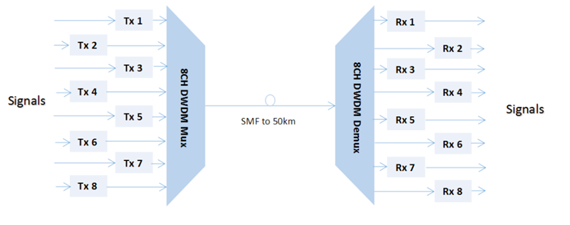
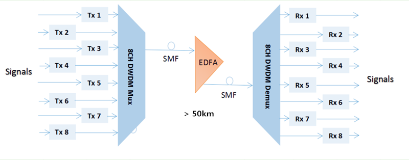
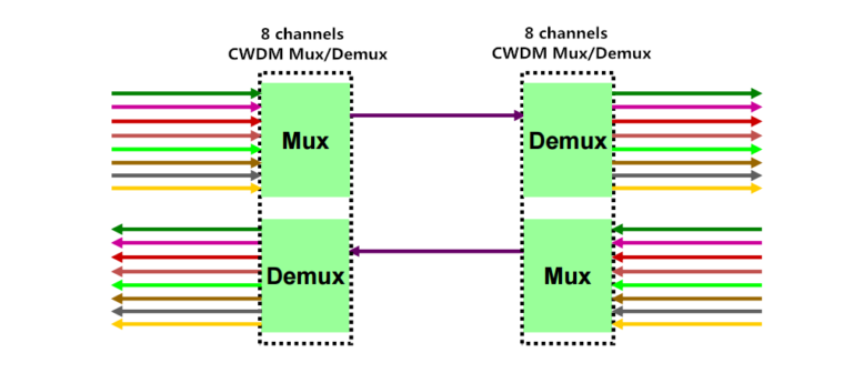
10G CWDM Point-to-Point Network: it is the simplest network infrastructure of the CWDM networks. As shown in the following figure, there are two passive CWDM Mux Demux deployed in the 10G network that offers 8 channels to multiplex the signals from 8 different optical fiber link into an integrated signal. Thereby, the signal can be transmit through only one fiber, which means there are 7 virtual fiber created with higher capacity for transmitting more data. As for the cheap passive CWDM Mux Demux, it can be available at very good price that costs less than upgrading the system from 10G to 40G or 100G. Undoubtedly, deploying a 10G CWDM point-to-point network is very economical solution for higher capacity.

10G CWDM Point-to-Point Network with CWDM Mux Demux

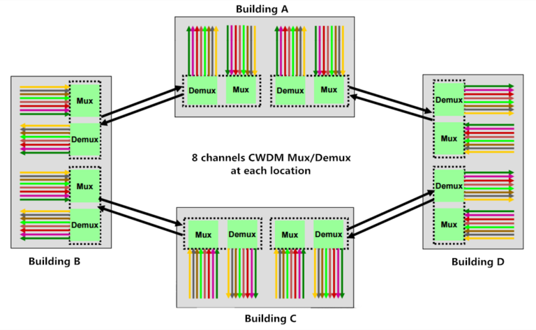
10G CWDM Ring Network: it is deployed on the basis of 10G CWDM point-to-point network. Compared to point-to-point network, the ring network is much more complex that needs other optical CWDM components like CWDM OADM. By adding CWDM OADM, two or more point-to-point network can be connected together, which can finally achieve a 10G CWDM ring network. To better understand how does the 10G CWDM ring network work, here offer a figure that shows four buildings are connected by several 8 channels CWDM Mux Demux and CWDM OADM for your reference.

10G CWDM Ring Network with CWDM Mux Demux

Conclusion
Unlike upgrading the network from 10G to 40G or 100G, building a 10G CWDM network doesn’t requires changing all the network equipment which may cost highly. It only need CWDM transceiver and CWDM Mux Demux to be deployed in the original 10G network. For a complex 10G CWDM network, additional optical equipment like CWDM OADM are required. If you come across the capacity-hungry issue, building a 10G CWDM network would be a nice option for higher capacity.

Wednesday, May 24, 2017

How to Extend Your Network Transmission Distance?

To face the need for long-haul, high-capacity transmission, experts come up with several DWDM projects including DWDM Mux Demux, EDFA amplifier (erbium-doped fiber amplifier) and DCM module (dispersion compensation module) to expand network capacity and enhance the signal power, which can greatly extend the optical network reach. Do you have the need to deploy a longer fiber optical transmission link? If yes, you can just build a DWDM system with the DWDM projects mentioned above. This paper will introduce three solutions that utilize these DWDM components to extend the optical network transmission distance. Hope these DWDM solutions would be useful for you.

Using DWDM Mux Demux for Long Transmission up to 50 km
DWDM technology plays an important role in building long-haul transmission system, which enables multiple signals with different wavelengths to be transmitted through only one single fiber. To build a long system with DWDM technology, the DWDM Mux Demux is an indispensable component that features low insertion loss and polarization-dependent loss. By using the DWDM Mux Demux in your network, the signal transmission distance can be extended to up to 50 km. To better know the advantage of DWDM Mux Demux, here offers an example that uses two 8 channel DWDM Mux Demux for extending the optical fiber link.

8 channel DWDM Mux Demux for Long transmission

From the figure, we can learn that at the transmit side, eight kinds of signals from different fiber links are multiplexed into an integrated signal by the 8 channel DWDM Mux. Then the integrated signal is transmitted over the single mode fiber (SMF) and the maximum transmission distance can be up to 50 km. At the receiver side, the signal will be demultiplexed into individual signals with their original wavelengths by the 8 channel DWDM Demux and then transmitted to another eight different fiber links. Just by using the DWDM Mux Demux, a 50km long-haul transmission can be simply achieved.

Adding EDFA Amplifier for Transmission Longer Than 50 km
As we know, the longer the transmission distance is, the higher the fiber loss will be. Hence, except for the DWDM Mux Demux, you are suggested to add an EDFA amplifier to the long fiber link if the transmission distance is longer than 50 km. What’s the function of EDFA amplifier? It is mainly designed to amplify the signal power, which enables longer transmission. As shown in the following figure, you can learn that the only difference is the EDFA amplifier in the SMF, compared to the first solution.

EDFA and 8 channel DWDM Mux Demux for Long transmission

When the integrated signal multiplexed by the 8 channel DWDM Demux is transmitted over the SMF, it would become too weak in the transmission process to be transmitted. Then the EDFA amplifier should be placed there to boost the signal power, supporting the transmission longer than 50 km. Once the long transmission is realized, the signal will be also split by the 8 channel DWDM Demux, like the first solution. In short, DWDM Mux Demux and EDFA amplifier are highly suggested if you want to deploy a DWDM system longer than 50 km.

Adding DCM Module for Transmission up to 200 km
With the use of EDFA amplifier, the DWDM fiber link can be extended to 200 km. However, the signal quality is always unsatisfied due to the optical dispersion in long transmission, especially in CATV systems. To meet high requirements of the signal quality in these long transmission systems, an additional optical component, DCM module are needed in the long fiber link, as deployed in the figure below.

DCM, EDFA and 8 channel DWDM Mux Demux for Long transmission

From the figure, we can learn it is a long-haul point-to-multipoint CATV system. To extend the transmission distance, 8 channel DWDM Mux Demux, EDFA amplifier are used. Except for that, a DCM module is added to enhance the skew signal for ensuring the whole transmission quality. With the use of DCM module, the accumulated chromatic dispersion issue is solved, without dropping and regenerating the wavelengths on the long fiber link. Thereby, a high-performance 200km system can be reached.

Conclusion
DWDM projects including DWDM Mux Demux, EDFA amplifier and DCM module are key optical components to support long-haul transmission systems. If you want to deploy a long transmission system up to 50 km, then the DWDM Mux Demux is needed. For transmission longer than 50 km, both the DWDM Mux Demux and EDFA amplifier are required for boost the signal power. But once the transmission distance is about 200 km, you should additionally add the DCM module to enhance the signal quality.

Friday, May 19, 2017

Whether to Use EDFA Amplifier in Long WDM System Or Not?

Currently, utilizing WDM technology to deploy the optical network has received widespread attentions, which enables higher capacity for data transmission. However, the technology is also limited by the transmission distance. When deploying a long WDM system, the signal power would still become weak due to the fiber loss. In order to address the issue, using EDFA amplifier to directly enhance the WDM signals would be a good choice for current and future optical network needs. The optical network combining WDM technology and EDFA module together can transmit multiple signals over the same fiber, at lengths up to a few hundred kilometers or even transoceanic distances. To better know how does EDFA amplifier work in the long WDM system, let’s learn the EDFA amplifier knowledge and analyze the performance of WDM system bonding with the EDFA module.

Introduction to EDFA Amplifier

EDFA amplifier, also referred to as erbium-doped fiber amplifier, is basically composed of a length of Erbium-doped fiber (EDF), a pump laser, and a WDM combiner. When it works, the pump laser with 980 nm or 1480 nm and the input signal around 1550 nm can be combined by the WDM combiner, then transmitted and multiplexed into the Erbium-doped fiber for signal amplification. The pump energy can be transmitted in the same direction as the signal (forward pumping), or the opposite direction to the signal (backward pumping), or both direction together. And the pump laser can also using 980 nm or 1480 nm, or both. Taking the cost, reliability and power consumption into account, the forward pumping configuration with 980nm pump laser EDFA amplifier is always the first choice to enhance the signals for a long WDM system.

Analysis of WDM Network Without EDFA Amplifier

Before analyzing WDM network deployed with EDFA amplifier, it is necessary to know the basic configuration of an original WDM network, as shown in the figure below. We can learn that four signals from different channels are combined by the optical combiner. And then, the integrated signals are transmitted through an optical fiber. Thirdly, the signals are split into two parts by the splitter. One part passes through the optical spectrum analyzer for analyzing signals, and the other one goes through the photo detector to be converted into electrical signal and then be observed by the electrical filter and scope. However, in the process, the signal power gets highly attenuated after being transmitting at long distance.

WDM System Without EDFA

Analysis of WDM Network Using EDFA Amplifier

By using the EDFA amplifier, we can easily overcome the attenuation of long WDM network. From the following figure, we can learn that EDFA amplifiers act as booster amplifier and pre-amplifier to enhance the signal, so that system will no longer suffer from losses or attenuation. Therefore, if you need to deploy a long WDM system, it is highly recommended to deploy the EDFA amplifiers in the system that features flat gain over a large dynamic gain range, low noise, high saturation output power and stable operation with excellent transient suppression. It is an undoubtedly ideal solution with reliable performance and relatively low cost to extend the WDM network transmission distance.

WDM System with EDFA

Conclusion

It is well know that the signal power would be greatly attenuated when the transmission distance is long enough. Hence, when deploying a long WDM network, it is definitely necessary to use the EDFA amplifier to enhance the signal strength, allowing for the long transmission distance. As a preferable option, the EDFA amplifier with very low noise is relatively insensitive to signal polarization and easy to realize signal amplification.

Wednesday, May 17, 2017

EDFA vs Raman Optical Amplifier

Although the fiber loss limits the transmission distance, the need for longer fiber optical transmission link seems never ending. In the pursuit of progress, several kinds of optical amplifiers are published to enhance the signals. Hence, longer fiber optical transmission link with big capacity and fast transmission rate can be achieved. As the EDFA and Raman amplifiers are the two main options for optical signal amplification. which one should be used when designing long fiber optical network? What are the differences of the two optical amplifiers? Which one would perform better to achieve the long fiber optical link? And which one is more cost effective? Let’s talk about this topics.

What’s EDFA Amplifier?
EDFA (Erbium-doped Fiber Amplifier), firstly invented in 1987 for commercial use, is the most deployed optical amplifier in the DWDM system that uses the Erbium-doped fiber as optical amplification medium to directly enhance the signals. It enables instantaneous amplification for signals with multiple wavelengths, basically within two bands. One is the Conventional, or C-band, approximately from 1525 nm to 1565 nm, and the other is the Long, or L-band, approximately from 1570 nm to 1610 nm. Meanwhile, it has two commonly used pumping bands, 980 nm and 1480 nm. The 980nm band has a higher absorption cross-section usually used in low-noise application, while 1480nm band has a lower but broader absorption cross-section that is generally used for higher power amplifiers.

The following figure detailedly illustrates how the EDFA amplifier enhance the signals. When the EDFA amplifier works, it offers a pump laser with 980 nm or 1480 nm. Once the pump laser and the input signals pass through the coupler, they will be multiplexed over the Erbium-doped fiber. Through the interaction with the doping ions, the signal amplification can be finally achieved. This all-optical amplifier not only greatly lowers the cost but highly improves the efficiency for optical signal amplification. In short, the EDFA amplifier is a milestone in the history of fiber optics that can directly amplify signals with multiple wavelengths over one fiber, instead of optical-electrical-optical signal amplification.

EDFA Amplifier Principle

What’s Raman Amplifier?
As the limitations of EDFA amplifier working band and bandwidth became more and more obvious, Raman amplifier was put forward as an advanced optical amplifier that enhances the signals by stimulated Raman scattering. To meet the future-proof network needs, it can provide gain at any wavelength. At present, two kinds of Raman amplifiers are available on the market. One is lumped Raman amplifier that always uses the DCF (dispersion compensation fiber) or high nonlinear fiber as gain medium. Its gain fiber is relatively short, generally within 10 km. The other one is distributed Raman amplifier. Its gain medium is common fiber, which is much longer, generally dozens of kilometers.

When the Raman amplifier is working, the pump laser may be coupled into the transmission fiber in the same direction as the signal (co-directional pumping), in the opposite direction (contra-directional pumping) or in both directions. Then the signals and pump laser will be nonlinearly interacted within the optical fiber for signal amplification. In general, the contra-directional pumping is more common as the transfer of noise from the pump to the signal is reduced, as shown in the following figure.

Raman Amplifier Principle

EDFA vs Raman Optical Amplifier: Which One Wins?
After knowing the basic information of EDFA and Raman optical amplifiers, you must consider that the Raman amplifier performs better for two main reasons. Firstly, it has a wide band, while the band of EDFA is only from 1525 nm to 1565 nm and 1570 nm to 1610 nm. Secondly, it enables distributed amplification within the transmission fiber. As the transmission fiber is used as gain medium in the Raman amplifier, it can increase the length of spans between the amplifiers and regeneration sites. Except for the two advantages mentioned above, Raman amplifier can be also used to extend EDFA.

However, if the Raman amplifier is a better option, why there are still so many users choosing the EDFA amplifiers? Compared with Raman amplifier, EDFA amplifier also features many advantages, such as, low cost, high pump power utilization, high energy conversion efficiency, good gain stability and high gain with little cross-talk. Here offers a table that shows the differences between EDFA and Raman optical amplifiers for your reference.


Considering that both EDFA and Raman optical amplifiers have their own advantages, which one should be used for enhancing signals, EDFA amplifier, Raman amplifier or both? It strictly depends on the requirement of your fiber optical link. You should just take the characteristics of your fiber optical link like length, fiber type, attenuation, and channel count into account for network design. When the EDFA amplifier meets the need, you don’t need the Raman amplifier as the Raman amplifier will cost you more.

Tuesday, May 9, 2017

How to Enhance the Optical Signals for a Long DWDM System?

As we know, the longer the optical transmission distance is, the weaker the optical signals will be. For a long DWDM system, this phenomenon easily causes transmission error or even failure. Under this case, what can we do for a smooth, long DWDM system? The answer is optical signal enhancement. Only by enhancing the optical signals, can the DWDM transmission distance be extended. In this post, we are going to learn two effective solutions, optical amplifier (OA) and dispersion compensating module (DCM) to enhance the signals, for making a smooth, long DWDM system.

Optical Amplifier Solution
We used to utilize repeater to enhance the signals in fiber optics, which should firstly convert the optical signals into an electrical one, amplify the electrical signals, and then convert the electrical signals into an optical one again. Finally, you can get the enhanced optical signals. However, this method of enhancing signals can not only cause more signal loss, but also add unwanted noises in the actual signal. Taking these issues into account, the optical amplifier is more recommendable.

An optical amplifier is a device that enables direct optical signal enhancement or amplification. Its working principle is not so complicated as that of the repeater, while its performance is much higher. From the following figure, we can learn that the original reach of the DWDM system is limited to 80 km due to the signal loss. But with the optical amplifier, the signals are enhanced and the reach can be extended to 160 km. It is really an ideal option to enhance the signals for a long DWDM system.

Optical Amplifier (OA)
At present, there are mainly three major kinds of optical amplifiers, Semiconductor Optical Amplifier (SOA), Doper Fiber Amplifier (DFA), and Raman Amplifier (RA).

Semiconductor Optical Amplifier: as its name implies, the semiconductor in a SOA is used to offer the gain medium. This kind of optical amplifier has a similar structure to the FP laser diode. However, it is designed with anti-reflection elements at the end face that can greatly reduce the end face reflection. Meanwhile, the SOA features small package and low cost that suits for most users to enhance the optical signals.

Doper Fiber Amplifier: in a DFA, the doped optical fiber acts as the gain medium for signal amplification. When the DFA works, the signal to be amplified and a pump laser are multiplexed into the doped fiber. And then the signal is amplified through interaction with the doping ions. The most common DFA is the Erbium Doped Fiber Amplifier (EDFA). Its gain medium is a optical fiber doped with trivalent erbium ions that always enhances the signals near 1550nm wavelength. Undoubtedly, the EDFA is a great choice to enhance the optical signals.

Raman Amplifier: different from the SOA and DFA, the signal in a RA is amplified through the nonlinear interaction between the signal and a pump laser within an optical fiber. In details, two kinds, distributed and lumped Raman amplifier (DRA and LRA) are available on the market. The distributed one multiplexes the pump wavelength with signal wavelength through the transmission fiber to enhance the signals, while the amplification of the lumped one is provided by a dedicated, shorter length of fiber.

Dispersion Compensating Solution
Apart from signal amplification, we can also use dispersion compensation to enhance the optical signals. Once the dispersion occurs, the signal will be tended to skew due to the different frequencies, which has a negative effect on the quality of signal transmission. At that moment, we use the dispersion compensating module to enhance the skew signal, for achieving a longer transmission distance. As shown in the figure below, the DWDM system is extended to longer than 80 km with the use of 80km passive dispersion compensating module.

Dispersion Compensating Module (DCM)

The dispersion compensation module is an important component for a long fiber optical link. It typically connects to the mid-stage of an OA like EDFA, in the long haul transmission system. Except for the 80km DCM mentioned above, FS.COM also provides other DCM modules that allow long transmission distance extension. The compensation distances can range from 10km to 140 km, as shown in the following table.

Dispersion Compensation Module

The optical amplifier has the ability to directly boost the weak signal, while the dispersion compensation module can reshape the deformed signal and offer a long compensation distance. Considering that the signal strength would become weak as the transmission distance increases, using the optical amplifier and dispersion compensation module to enhance the signals is very necessary when building a long DWDM system.

Conclusion
The optical amplifier has the ability to directly boost the weak signal, while the dispersion compensation module can reshape the deformed signal and offer a long compensation distance. Considering that the signal strength would become weak as the transmission distance increases, using the optical amplifier and dispersion compensation module to enhance the signals is very necessary when building a long DWDM system.

Thursday, May 4, 2017

Economical Solutions for 10G to 40G Connection

With the accelerated development of optical network, there exist more and more capacity-hungry applications in 10G networks today. To solve this problem, experts put forward the 10G to 40G connection as an ideal solution. However, due to the high migration cost, we are prevented from making the migration. Do you also meet this issue? In this paper, it will offer several solutions for making 10G to 40G connections with less cost. Hope you can find one that suits your network.

10G to 40G Connection

Economical Solutions for 10G to 40G Short Connection
How to make a short link between 10G and 40G switches? You can choose the 40GBASE-SR4 QSFP+ module that supports the 40G network at length up to 150 m. Meanwhile, four 10GBASE-SR SFP+ modules are required. So is the MTP-LC harness cable for connecting QSFP+ and four SFP+ modules. In details, FS.COM offers OM3 MTP-LC harness cable supporting 40G connection up to 100 m and OM4 up to150 m. All these equipment mentioned above are available at FS.COM with good prices. For the details, you can learn from the following table.


http://www.chinacablesbuy.com/wp-content/uploads/2017/05/Economical-Solutions-for-10G-to-40G-Short-Connection.jpg

If the link distance is longer than 150 m in your network, 40GBASE-CSR4 QSFP+ module may be a better choice. It can transmit the 40G signals longer, up to 400 m. As for the fiber patch cable, you can still chosse OM3 or OM4 MTP-LC harness cable. In general, the OM3 provided by FS.COM enables the connection up to 300 m, while OM4 up to 400 m. When making a short 10G to 40G migration, you can just choose FS.COM as an ideal fiber optical manufacturer. It offers all the equipment your network needs, including 10G and 40G switches, SFP+ and QSFP+ module and MTP-LC patch cable.

Economical Solutions for 10G to 40G Long Connection
Do you need to make a long 10G to 40G migration? FS.COM also offers several cost effective solutions. For example, up to 1km, 10km, 40km or even 80km 10G to 40G connection solutions. Let’s talk about the detail information of these solutions.

Spending Less for up to 40km 10G to 40G Connection


You can use the 40GBASE-PLRL4 QSFP+ and 10GBASE-LR SFP+ modules to support the 10G to 40G migration up to 1 km. The 40GBASE-LRL4 QSFP+ is also a good choice. As for the fiber patch cable, you can choose the 8 fibers single mode MTP-LC harness cable. Once the distance is longer than 1 km, your are suggested to use the 40GBASE-LR4 QSFP+ and 40GBASE-PLR4 QSFP+ modules. These two kinds of fiber transceiver modules enable the connection at lengths up to 10 km. It the link distance is up to 40 km, then you can use the 40GBASE-ER4 QSFP+ module. Here are the related equipment offered by FS.COM.

Economical Solutions for 10G to 40G Long Connection

Spending Less for up to 80km 10G to 40G Connection


Have you ever felt puzzled about whether the 10G to 40G connection can be extended to 80 km? Here you’ll find the answer is yes. How to deploy 80km 10G to 40G connection? You should add the extra equipment, including two DWDM Mux Demux, two WDM transponder OEO (Optical-Electrical-Optical) repeaters and several DWDM SFP+ modules, to your network.

In order to make a smooth 80km 10G to 40G migration, we should add the WDM transponder OEO repeater into the 10G to 40G link. It can not only act as fiber repeater for long distance transmission, but also CWDM/DWDM optical wavelength converter. When the 10G signals pass through the WDM transponder OEO repeater, it will be converted into several DWDM singals. Then you should use the DWDM Mux Demux to multiplex, transmit and demultiplex them. And finally another WDM transponder OEO repeater is required to convert the DWDM singals into 10G signals again. Hence, you can finally achieve the up to 80km 10G to 40G connection. As for the equipment the network requires, you can also order them from FS.COM with good prices.

Spending Less for up to 80km 10G to 40G Connection

Conclusion
FS.COM is an ideal fiber optical manufacturer that offers very cost effective solutions for 10G to 40G connection. These solution can support not only the short 10G to 40G migration at lengths up to 400 m, but also the long migration with reach 1km, 10km or even up to 40km. Moreover, if you want to extend the 10G to 40G connection up to 80 km, you can order the extra equipment like DWDM Mux Demux, WDM transponder OEO repeaters and DWDM SFP+ modules from FS.COM with good price. All the equipment mentioned above have been tested to assure 100% compatibility.

Original source: http://www.chinacablesbuy.com/economical-solutions-for-10g-to-40g-connection.html